Sign In
Upload
Download
Table of Contents
Contents
Add to my manuals
Delete from my manuals
Share
URL of this page:
HTML Link:
Bookmark this page
Add
Manual will be automatically added to "My Manuals"
Print this page
×
Bookmark added
×
Added to my manuals
Manuals
Brands
Simrad Manuals
Radio
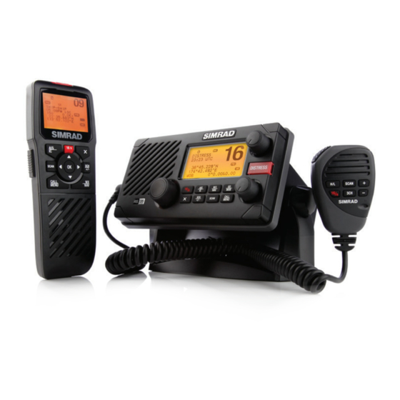
RS35 VHF HS35
Installation instructions manual
Simrad RS35 VHF Installation Instructions Manual
Hide thumbs
Also See for RS35 VHF
:
User manual
(92 pages)
1
2
Table Of Contents
3
4
5
6
7
8
9
10
11
12
13
14
15
16
17
18
19
20
21
22
page
of
22
Go
/
22
Contents
Table of Contents
Bookmarks
Table of Contents
Table of Contents
Important Safety Information
1 Installation Preparation
Checklist
Tools Needed for Installation
2 VHF Installation
Location Requirements
LCD Viewing Angle
Choose an Installation Type
Mounting Bracket Installation
Recessed Installation
RS35 Dimensions
Handset MIC Wall Hanger
3 VHF Electrical Installation
Connect the Radio
Wiring Diagram - NMEA 2000 Connections
Wiring Diagram - External Speaker and Hailer
Wiring Diagram - NMEA 0183 Connections
4 HS35 Handset Installation
5 Setup Your Radio - Your User MMSI
Advertisement
Quick Links
1
Rs35 Dimensions
2
Connect the Radio
3
Vhf Electrical Installation
4
Wiring Diagram - Nmea 2000 Connections
5
Wiring Diagram - External Speaker and Hailer
6
Wiring Diagram - Nmea 0183 Connections
7
Setup Your Radio - Your User Mmsi
Download this manual
See also:
User Manual
RS35 VHF
HS35 Handset
Installation Instructions
ENGLISH
simrad-yachting.com
Table of
Contents
Previous
Page
Next
Page
1
2
3
4
5
Advertisement
Table of Contents
Need help?
Do you have a question about the RS35 VHF and is the answer not in the manual?
Ask a question
Questions and answers
Related Manuals for Simrad RS35 VHF
Handsets Simrad RS35 VHF HS35 User Manual
(92 pages)
Radio Simrad RS86 Manual
Vhf radio systems (88 pages)
Radio Simrad RS90 Installation Manual
(29 pages)
Radio Simrad Shipmate RS8400 Introduction Manual
Vhf radiotelephones (34 pages)
Radio Simrad Shipmate RS8300 SOS Introduction Manual
Vhf radiotelephones (34 pages)
Radio Simrad RS25/AHK05 Quick Start Manual
(16 pages)
Radio Simrad SHIPMATE RS8100 Operator's Manual
(39 pages)
Radio Simrad RS10U Manual
(56 pages)
Radio Simrad RS10E Manual
(56 pages)
Radio Simrad RS81 Instruction Manual
(51 pages)
Radio Simrad RS82 Instruction Manual
(51 pages)
Radio Simrad RS90S User Manual
Blackbox vhf (134 pages)
Radio Simrad RS90S Quick Start Manual
Blackbox vhf (4 pages)
Radio Simrad RS40 User Manual
Fixed mount vhf & wireless handset (88 pages)
Radio Simrad RS20 User Manual
(60 pages)
Radio Simrad RS20S User Manual
Fixed mount vhf (54 pages)
This manual is also suitable for:
Hs35 handset
Table of Contents
Save PDF
Print
Rename the bookmark
Delete bookmark?
Delete from my manuals?
Login
Sign In
OR
Sign in with Facebook
Sign in with Google
Upload manual
Upload from disk
Upload from URL


Need help?
Do you have a question about the RS35 VHF and is the answer not in the manual?
Questions and answers