Table of Contents
Advertisement
Quick Links
Advertisement
Table of Contents

Related Manuals for Planet WNAP-7300


Summary of Contents for Planet WNAP-7300
- Page 1 802.11a/n Outdoor Wireless CPE AP/Router WNAP-7300 User’s Manual Version 1.0...
- Page 2 Copyright Copyright© 2011 by PLANET Technology Corp. All rights reserved. No part of this publication may be reproduced, transmitted, transcribed, stored in a retrieval system, or translated into any language or computer language, in any form or by any means, electronic, mechanical, magnetic, optical, chemical, manual or otherwise, without the prior written permission of PLANET.
- Page 3 dependent and are firmware programmed at the factory to match the intended destination. The firmware setting is not accessible by the end user. CE Mark Warning This is a Class B product. In a domestic environment, this product may cause radio interference, in which case the user may be required to take adequate measures.
- Page 4 Do not dispose of WEEE as unsorted municipal waste and have to collect such WEEE separately. Revision User’s Manual for PLANET 802.11a/n Outdoor Wireless CPE AP/Router Model: WNAP-7300 Rev: 1.0 (January, 2011)
-
Page 5: About This Manual
About This Manual This user manual is intended to guide professional installer to install the WNAP-7300 and how to build the infrastructure centered on it. It includes procedures to assist you in avoiding unforeseen problems. Conventions For your attention on important parts, special characters and patterns are used in this manual: Note: This indicates an important note that you must pay attention to. -
Page 6: Table Of Contents
Content Chapter 1 Introduction......................... 1 1.1 Introduction........................... 1 1.2 Appearance ..........................1 1.3 Key Features ..........................2 1.4 Typical Application ........................2 Chapter 2 Hardware Installation ......................3 2.1 Preparation before Installation...................... 3 2.1.1 Professional Installation Required ..................3 2.1.2 Safety Precautions......................... 3 2.1.3 Installation Precautions...................... - Page 7 4.2.2 Access Control ........................36 4.2.3 WDS Settings........................37 Chapter 5 Management........................38 5.1 SNMP Management ........................38 5.1.1 Configure SNMPv3 User Profile ..................39 5.2 Upgrade Firmware........................40 5.3 Backup/ Retrieve Settings ......................42 5.4 Restore Factory Default Settings ....................43 5.5 Reboot ............................
- Page 8 FIGURE Figure 1 WNAP-7300 ..........................1 Figure 2 Typical Application ........................2 Figure 3 Move the Cover........................6 Figure 4 Cable Connection ........................6 Figure 5 Enable the Secondary RJ45 Power..................7 Figure 6 Power on the device by PWR button ..................7 Figure 7 Attach and fasten the removable cover ...................
- Page 9 Figure 32 WDS Settings........................37 Figure 33 SNMP Configuration ......................38 Figure 34 Configure SNMPv3 User Profile ..................39 Figure 35 Upgrade Firmware ....................... 41 Figure 36 Backup/Retrieve Settings ....................42 Figure 37 Restore Settings ........................43 Figure 38 Reboot ..........................44 Figure 39 Password ..........................
- Page 10 TABLE Table 1 Factory Default Settings ......................13 Table 2 ACSII………..........................57 Table 3 Public Software Name and Description……….……………………………………………………59...
-
Page 11: Chapter 1 Introduction
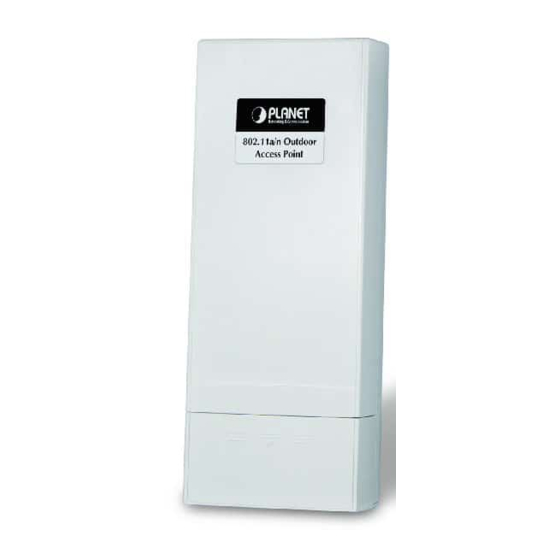
AP+WDS), allowing for various application requirements thus helping to find the key to the “last mile” with least effort. With high output power and reliable performance, the WNAP-7300 is an ideal wireless broadband solution for wireless Internet service providers and system integrators! 1.2 Appearance... -
Page 12: Key Features
User-friendly Web and SNMP-based management interface 1.4 Typical Application This section describes the typical applications of the WNAP-7300. By default, it is set to AP mode which allows it to establish a wireless coverage; besides, it is also able to join any available wireless network under wireless client mode. -
Page 13: Chapter 2 Hardware Installation
To keep you safe and install the hardware properly, please read and follow these safety precautions. If you are installing the WNAP-7300 for the first time, for your safety as well as others’, please seek assistance from a professional installer who has received safety training on the hazards involved. -
Page 14: Installation Precautions
2.1.3 Installation Precautions To keep the WNAP-7300 well while you are installing it, please read and follow these installation precautions. Users MUST use a proper and well-installed surge arrestor with the WNAP-7300; otherwise, a random lightening could easily cause fatal damage to the unit. - Page 15 Pole Mounting Ring Power Adapter & POE Injector Warning: Users MUST use the “Power Adapter & POE Injector” shipped in the box with the WNAP-7300. Use of other options will cause damage to the unit.
-
Page 16: Hardware Installation
2.2 Hardware Installation 2.2.1 Connect up The bottom of WNAP-7300 is a movable cover. Loosen the screw with a Phillips screwdriver. The bottom of WNAP-7300 is a movable cover. Loosen the screw with a Phillips screwdriver. Grab the cover and pull it out as the figure shown below. -
Page 17: Figure 5 Enable The Secondary Rj45 Power
※ The secondary Ethernet port (labeled LAN 2) is for IP video integration. To use it you need to enable the secondary port in advance before connecting with the IP camera from the WNAP-7300’s Web Management as shown below. Figure 5 Enable the Secondary RJ45 Power Press the black PWR button beside the LAN 1 Ethernet port. -
Page 18: Figure 7 Attach And Fasten The Removable Cover
Attach and fasten the removable cover to the bottom of the WNAP-7300. When finished, you can check the connection as the figure shown below. Figure 7 Attach and fasten the removable cover Plug the power cord into the DC port of the POE injector as the figure shown below. -
Page 19: Figure 9 Complete Set
Figure 9 Complete Set Note: Be reminded, the UTP wire distance toward your WNAP-7300 to the Ethernet devices, such as Ethernet Switch, is 100 meters, the passive POE injector can be in any point of this 100 meters UTP distance where there is a shell or protected location. -
Page 20: Using The External Antenna
2.2.2 Using the External Antenna The WNAP-7300 provides two reverse SMA antenna connectors if you prefer to use the external antenna for your application instead of the built-in directional antenna, please follow the steps below. Remove the two plugs as circled below: Figure 10 Remove the plugs Connect your external antenna to the SMA-type connectors at the bottom of the WNAP-7300. -
Page 21: Pole Mounting
Follow the steps described in Connect Up to finish the installation. 2.2.3 Pole Mounting Turn the WNAP-7300 over. Put the pole mounting rings through the middle hole of it. Note that you should unlock the pole mounting ring with a screw driver before putting it through the WNAP-7300 as the following right picture shows. -
Page 22: Figure 13 Pole Mounting – Step 2
Figure 13 Pole Mounting – Step 2 Now you have completed the hardware installation of the WNAP-7300.Basic Settings - 12 -... -
Page 23: Chapter 3 Basic Settings
Chapter 3 Basic Settings 3.1 Factory Default Settings We’ll elaborate the WNAP-7300 factory default settings. You can re-acquire these parameters by default. If necessary, please refer to the “Restore Factory Default Settings”. Table 1 Factory Default Settings Features Factory Default Settings... -
Page 24: System Requirements
3.3 How to Login the Web-based Interface The WNAP-7300 provides you with user-friendly Web-based management tool. Open Web browser and enter the IP address (Default: 192.168.1.1) of the WNAP-7300 into the address field. You will see the login page as below. -
Page 25: Figure 14 Login
Enter the username (Default: admin) and password (Default: admin) respectively and click “Login” to login the main page of the WNAP-7300. As you can see, this management interface provides six main options in the black bar above, which are Status, System, Wireless, Management and Tools. -
Page 26: Figure 15 Main
Figure 15 Main Page Note: The username and password are case-sensitive, and the password should be no more than 19 characters! - 16 -... -
Page 27: Basic System Settings
3.4 Basic System Settings For users who use the WNAP-7300 for the first time, it is recommended that you begin configuration from “Basic Settings” in “System” shown below: Figure 16 Basic System Settings Basic Settings Device Name: Specify the device name, which is composed of no more than 15 characters with (0-9), (A-Z), (a-z) or (-). -
Page 28: Figure 17 Tcp/Ip Settings (Bridge)
TCP/IP Settings Open “TCP/IP Settings” in “System” as below to configure the parameters for LAN which connects to the LAN port of the WNAP-7300. In this page, users may change the settings for IP Address, Subnet Mask, and DHCP Server. -
Page 29: Figure 18 Tcp/Ip Settings (Router)
Note: When the IP address of the WNAP-7300 is changed, the clients on the network often need to wait for a while or even reboot before they can access the new IP address. For an immediate access to the bridge, please flush the netbios cache on the client computer by running the “nbtstat –r”... -
Page 30: Time Settings
LAN Settings: When DHCP Server is disabled, users can specify IP address and subnet mask for the WNAP-7300 manually. Make sure the specified IP address is unique on your network in order to prevent IP conflict. When DHCP Server is enabled, users may specify DHCP IP Address Range, DHCP Subnet Mask, DHCP Gateway and Lease Time (15-44640 minutes). -
Page 31: Radius Settings
Figure 19 Time Settings Current Time Display the present time in Yr, Mon, Day, Hr, Min and Sec. Time Zone Select Select the time zone from the dropdown list. NTP Server Select the time server from the “NTP Server” dropdown list or manually input the IP address of available time server into “Manual IP”. -
Page 32: Figure 20 Radius Settings
Figure 20 RADIUS Settings Authentication RADIUS Server This is for RADIUS authentication. It can communicate with RADIUS through IP Address, Port and Shared Secret. IP Address: Enter the IP address of the Radius Server; Port: Enter the port number of the Radius Server; Shared Secret: This secret, which is composed of no more than 31 characters, is shared by the AP and RADIUS during authentication. -
Page 33: Firewall Settings
Source IP Filtering: The source IP filtering gives users the ability to restrict certain types of data packets from your local network to Internet through the WNAP-7300. Use of such filters can be helpful in securing or restricting your local network. -
Page 34: Figure 22 Destination Ip Filtering
Figure 22 Destination IP Filtering Source Port Filtering: The source port filtering enable you to restrict certain ports of data packets from your local network to Internet through the WNAP-7300. Use of such filters can be helpful in securing or restricting your local network. -
Page 35: Figure 24 Destination Port Filtering
Internet through the WNAP-7300. Use of such filters can be helpful in securing or restricting your local network. Figure 24 Destination Port Filtering Port Forwarding: The port forwarding allows you to automatically redirect common network services to a specific machine behind the NAT firewall. -
Page 36: Figure 25 Port Forwarding
Figure 25 Port Forwarding DMZ: A Demilitarized Zone is used to provide Internet services without sacrificing unauthorized access to its local private network. Typically, the DMZ host contains devices accessible to the Internet traffic, such as Web (HTTP) servers, FTP servers, SMTP (e-mail) servers and DNS servers. Figure 26 DMZ... -
Page 37: Basic Wireless Settings
AP: The WNAP-7300 establishes a wireless coverage and receives connectivity from other wireless devices. Wireless Client: The WNAP-7300 is able to connect to the AP and thus join the wireless network around it. Bridge: The WNAP-7300 establishes wireless connectivity with other APs by keying in remote MAC address. - Page 38 In AP mode, hiding network name is necessary when you are in a wireless environment that may have potential risk. By disabling broadcast SSID, the STA cannot scan and find the WNAP-7300, so that malicious attack by some illegal STA could be avoided.
- Page 39 Compared to CTS-Self; the transmission amount of CTS-RTS is much lower. Enable MAC Clone Available only under wireless client mode, it hides the MAC address of the WNAP-7300 while displays the one of associated wireless client or the MAC address designated manually.
-
Page 40: Site Survey
3.9 Site Survey Under wireless client mode, the WNAP-7300 is able to perform site survey, through which, information on the available access points will be detected. Open “Basic Settings” in “Wireless”, by clicking the “Site Survey” button beside “Wireless Mode”... -
Page 41: Chapter 4 Advanced Settings
Chapter 4 Advanced Settings 4.1 Advanced Wireless Settings Open “Advanced Settings” in “Wireless” to make advanced wireless settings. Figure 29 Advanced Wireless Settings WMM Support WMM (Wi-Fi Multimedia) is a subset of 802.11e. It allows wireless communication to define a priority limit on the basis of data type under AP mode only, thus those time-sensitive data, like video/audio data, may own a higher priority than common one. - Page 42 A-MPDU/A-MSDU Aggregation The data rate of your WNAP-7300 except wireless client mode could be enhanced greatly with this option enabled; however, if your wireless clients don’t support A-MPDU/A-MSDU aggregation, it is not recommended to enable it. Short GI Under 802.11n mode, enable it to obtain better data rate if there is no negative compatibility issue.
- Page 43 Available only under AP mode, it defines the maximum amount of wireless clients allowed to be connected. Space in Meter/ACK Timeout To decrease the chances of data retransmission at long distance, the WNAP-7300 can automatically adjust proper ACK timeout value by specifying distance of the two nodes. Flow Control It allows the administrator to specify the incoming and outgoing traffic limit by checking “Enable...
-
Page 44: Wireless Security Settings
4.2 Wireless Security Settings To prevent unauthorized radios from accessing data transmitting over the connectivity, the WNAP-7300 provides you with rock solid security settings. 4.2.1 Security Settings Open “Security Settings” in “Wireless” as below: Figure 30 Security Settings Network Authentication Open System: It allows any device to join the network without performing any security check. - Page 45 WPA with RADIUS: With warrant (username, password and etc.) offered by user, this kind of authentication can be realized with specific RADIUS server. This is the common way to be adopted in large enterprise network. WPA2 with RADIUS: As a new version of WPA, only all the clients support WPA2, can it be available.
-
Page 46: Access Control
4.2.2 Access Control The Access Control appoints the authority to wireless client on accessing the WNAP-7300, thus a further security mechanism is provided. This function is available only under AP mode. -
Page 47: Wds Settings
Distribution System (WDS): Simply put, you can link the bridges wirelessly. Open “WDS Settings” in “Wireless” as below: Figure 32 WDS Settings Enter the MAC address of another WNAP-7300 you wirelessly want to connect to into the appropriate field and click “Apply” to save settings. Note:... -
Page 48: Chapter 5 Management
Check this box to enable SNMP settings. Protocol Version Select the SNMP version, and keep it identical on the WNAP-7300 and the SNMP manager. Server Port Change the server port for a service if needed; however you have to use the same port to use that... -
Page 49: Configure Snmpv3 User Profile
Get Community Specify the password for the incoming Get and GetNext requests from the management station. By default, it is set to public and allows all requests. Set Community Specify the password for the incoming Set requests from the management station. By default, it is set to private. -
Page 50: Upgrade Firmware
User Name Specify a user name for the SNMPv3 administrator or user. Only the SNMP commands carrying this user name are allowed to access the WNAP-7300. Password Specify a password for the SNMPv3 administrator or user. Only the SNMP commands carrying this password are allowed to access the WNAP-7300. -
Page 51: Figure 35 Upgrade Firmware
Figure 35 Upgrade Firmware Click “Browse” to select the firmware file you would like to load; Click “Upload” to start the upload process; Wait a moment, the system will reboot after successful upgrade. Note: Do NOT cut the power off during upgrade, otherwise the system may crash! -
Page 52: Backup/ Retrieve Settings
5.3 Backup/ Retrieve Settings It is strongly recommended you back up configuration information in case of something unexpected. If tragedy hits your device, you may have an access to restore the important files by the backup. All these can be done by the local or remote computer. Open “Configuration File”... -
Page 53: Restore Factory Default Settings
Restore factory default settings via Reset Button If software in the WNAP-7300 is unexpectedly crashed and no longer reset the unit via Web, you may do hardware reset via the reset button. Press and hold the button for at least 5 seconds and then release it until the PWR LED gives a blink. -
Page 54: Password
Figure 38 Reboot 5.6 Password From “Password Settings” in “Management”, you can change the password to manage your WNAP-7300. Enter the new password respectively in “New Password” and “Confirm Password” fields; click “Apply” to save settings. -
Page 55: System Log
The password is case-sensitive and its length cannot exceed 19 characters! 5.7 System Log System log is used for recording events occurred on the WNAP-7300, including station connection, disconnection, system reboot and etc. Open “System Log” in “Tools” as below. -
Page 56: Site Survey
Figure 40 System Log Remote Syslog Server Enable Remote Syslog: Enable System log to alert remote server. IP Address: Specify the IP address of the remote server. Port: Specify the port number of the remote server. 5.8 Site Survey Only available under Wireless Client mode, site survey allows you to scan all the APs within coverage. Open “Site Survey”... -
Page 57: Ping Watch Dog
Figure 41 Site Survey Tool 5.9 Ping Watch Dog If you mess your connection up and cut off your ability the log in to the unit, the ping watchdog has a chance to reboot due to loss of connectivity. Figure 42 Ping Watchdog... - Page 58 IP Address to Ping: Specify the IP address of the remote unit to ping. Ping Interval: Specify the interval time to ping the remote unit. Startup Delay: Specify the startup delay time to prevent reboot before the WNAP-7300 is fully initialized.
-
Page 59: Chapter 6 Status
Chapter 6 Status 6.1 View Basic Information Open “Information” in “Status” to check the basic information of the WNAP-7300, which is read only. Click “Refresh” at the bottom to have the real-time information. Figure 43 Basic Information... -
Page 60: View Association List
6.2 View Association List Open “Association List” in “Connection” from “Status” to check the information of associated wireless clients. All is read only. Click “Refresh” at the bottom to view the current association list. Figure 44 Connection 6.3 View Network Flow Statistics Open “Flow Statistics”... -
Page 61: Figure 45 Network Flow Statistics
Figure 45 Network Flow Statistics Poll Interval Specify the refresh time interval in the box beside “Poll Interval” and click “Set Interval” to save settings. “Stop” helps to stop the auto refresh of network flow statistics. -
Page 62: View Arp Table
6.4 View ARP Table Open “ARP Table” in “Status” as below. Click “Refresh” to view current table. Figure 46 ARP Table 6.5 View Bridge Table Open “Bridge Table” in “Status” as below. Click “Refresh” to view current connected status. -
Page 63: View Active Dhcp Client Table
Figure 47 Bridge Table 6.6 View Active DHCP Client Table Open “DHCP Client List” in “Status” as below to check the assigned IP address, MAC address and time expired for each DHCP leased client. Click “Refresh” to view current table. Figure 48 DHCP Client Table... -
Page 64: Chapter 7 Troubleshooting
Chapter 7 Troubleshooting This chapter provides troubleshooting procedures for basic problems with the WNAP-7300. For warranty assistance, contact your service provider or distributor for the process. Q 1. How to know the MAC address of the WNAP-7300? MAC Address distinguishes itself by the unique identity among network devices. There are two ways available to know it. - Page 65 Q 5. In wireless client mode, what if the wireless connection is not stable after associating with an AP? • Since the WNAP-7300 comes with a built-in directional antenna, it is recommended make it face to the direction where the AP is to get the best connection quality. •...
-
Page 66: Appendix A. Ascii
Appendix A. ASCII WEP can be configured with a 64-bit, 128-bit or 152-bit Shared Key (hexadecimal number or ACSII). As defined, hexadecimal number is represented by 0-9, A-F or a-f; ACSII is represented by 0-9, A-F, a-f or punctuation. Each one consists of two-digit hexadecimal. Table 2 ACSII ASCII ASCII... -
Page 67: Appendix B. Gpl Declamation
Appendix B. GPL Declamation PUBLIC SOFTWARE DECLAMATION In the software we delivered, there may contains some public software, if it is, please read below carefully: 1. Definition “Public Software”, when applicable, shall mean that portion of the Licensed Software, in source code form, set forth in the below Table, and provided under the terms set forth in the Section 5, the indicated website, the complete license terms can be found. - Page 68 3. Limited Liability The supplier hereby express that the supplier shall have no liability for any costs, loss or damages resulting from Licensee’s breach of the terms and conditions applicable to use, conversion or combination of the licensed software with or into Public Software. 4.
- Page 69 hostapd Copyright (c) http://hostap.epit GNU GENERAL http://www.gnu.or 2002-2006, Jouni est.fi/releases/h PUBLIC LICENSE g/licenses/old-lice Malinen ostapd-0.4.8.tar. Version 2 nses/gpl-2.0.html <jkmaline@cc.hut.fi > and contributors wpa_sup Copyright (c) http://hostap.epit GNU GENERAL http://www.gnu.or plicant 2003-2005, Jouni est.fi/releases/w PUBLIC LICENSE g/licenses/old-lice Malinen pa_supplicant-0. Version 2 nses/gpl-2.0.html <jkmaline@cc.hut.fi 4.7.tar.gz...
- Page 70 iptables Copyright ftp://ftp.netfilter.o GNU GENERAL http://www.gnu.or 2000-2004 netfilter rg/pub/iptables/i PUBLIC LICENSE g/licenses/old-lice project ptables-1.3.6.tar. Version 2 nses/gpl-2.0.html http://www.netfilter.o openssl Copyright (c) http://www.open GNU GENERAL http://www.gnu.or 1998-2008 The ssl.org/source/o PUBLIC LICENSE g/licenses/old-lice OpenSSL Project. penssl-0.9.8k.tar Version 2 nses/gpl-2.0.html All rights reserved. Igmppro xy Copyright (C) 2005 http://sourceforg GNU GENERAL...
Need help?
Do you have a question about the WNAP-7300 and is the answer not in the manual?
Questions and answers