Advertisement
Quick Links
Download this manual
See also:
Owner's Manual
Quick Start Guide
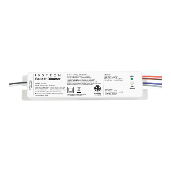
Ballast Dimmer
®
INSTEON
Remote Control 0-10VDC Ballast Dimmer or Dual Switch
Model: 2475DA2 (US), 2446-422 (EU), 2446-522 (AUS/NZ)
About Ballast Dimmer
This in-line ballast control module supports two different operational modes: dimmer and dual-relay. For use in new construction
or retrofit (inside or outside the fixture) where saving energy is a priority.
Line (Black)
Neutral (White)
RJ-10 Mini-modular jack pin-outs:
Pin 4
Pin 3
(Left side)
Ground
Group 1 - 2
Install Ballast Dimmer for Dimmable Ballast
Note: use with branch circuit breakers 15 Amperes or fewer.
Write down the INSTEON ID found on the front of the unit
1)
(XX.XX.XX)
Turn off breaker/fuse and verify that the power is off
2)
Disconnect wires from existing switch
3)
Connect wires per diagram
4)
At the ballast location, disconnect the wires from the fixture
5)
you will be controlling and ensure that you have ½ inch of
bare wire on the ends
See the diagram to identify and connect the line, load,
6)
neutral DC(+) and DC(-) wires on Ballast Dimmer. Be sure
you have correctly identified the wires in the junction box
before connecting them.
After ensuring wires are firmly connected and that there is
7)
2475DA2 Rev. 7/24/2013 8:55 AM / See Owner's Manual for Warranty Information.
Protected under U.S. and foreign patents (see www.insteon.com/patents)
© Copyright 2013 INSTEON, 16542 Millikan Ave., Irvine, CA 92606, 866-243-8022
Neutral (White)
Pin 2
Pin 1
Group 3-4
12-15VDC
Line (Black)
Status LED
Set button
Group 1: triggers when switch between pin 3 & 4 is closed
Group 2: triggers when switch between pin 3 & 4 is opened
Group 3: triggers when switch between pin 2 & 4 is closed
Group 4: triggers when switch between pin 2 & 4 is opened
no exposed wire, turn on breaker/fuse
After a few seconds, load will turn on
Test Ballast Dimmer connection by tapping set button a
8)
couple times
Ballast Dimmer load will respond appropriately
Link Ballast Dimmer to your INSTEON keypad or other
9)
INSTEON controller. See Make Ballast Dimmer a
.
Responder
Gently place Ballast Dimmer into the fixture box, making
10)
sure nothing could accidentally press on the set button
Reinstall the fixture
11)
The hot feeding this circuit is paralleled from the hot
connection on the keypad keeping both devices powered at
all times and using existing wiring.
Load 2 (Red)
Load 1 (Red/Black)
0-10VDC + (Purple)
DC ground (Grey)
RJ-10 jack
0-10VDC + (Purple)
DC ground (Grey)
Load 2 (Red)
Advertisement

Related Manuals for INSTEON 2475DA2


Summary of Contents for INSTEON 2475DA2
-
Page 1: About Ballast Dimmer
0-10VDC + (Purple) DC ground (Grey) Load 2 (Red) 2475DA2 Rev. 7/24/2013 8:55 AM / See Owner’s Manual for Warranty Information. Protected under U.S. and foreign patents (see www.insteon.com/patents) The hot feeding this circuit is paralleled from the hot © Copyright 2013 INSTEON, 16542 Millikan Ave., Irvine, CA 92606, 866-243-8022... -
Page 2: Make Ballast Dimmer A Responder
Test the Ballast Dimmer connection by tapping set button a couple times Link Ballast Dimmer to your INSTEON keypad or other INSTEON controller. See Make Ballast Dimmer a Responder Gently place Ballast Dimmer into the fixture box, making sure nothing could accidentally press the set button...