Woodway DESMO Assembly Directions
Hide thumbs
Also See for DESMO:
- User manual (136 pages) ,
- Service manual (97 pages) ,
- Owner's manual (83 pages)

Subscribe to Our Youtube Channel
Related Manuals for Woodway DESMO


Summary of Contents for Woodway DESMO
- Page 1 WOODWAY 4FRONT, DESMO. PATH, AND MERCURY TREADMILL ASSEMBLY DIRECTIONS "Woodway Treadmill Assembly Directions - ATTACHED Top arm assembly + 2 side plastics (4 pieces total)"...
- Page 2 The treadmill can be delivered in various states of assembly. Disassembly/assembly may be required for moves or relocation into other rooms. NOTE In WOODWAY performance and fitness treadmills, standard (inch) screws and nuts are used, with few exceptions. These are not compatible with metric fastening elements!
- Page 3 Insert wire and protective cover into the handrail tube to prevent damage during insertion. Fig. 16 4Front assembly, wiring Prepare the mount for the tube. Fig. 17 4Front assembly, tube mount Insert the handrail tube into the mounts. Note: Do not damage the wires! Be careful not to pinch yourself!
- Page 4 Pull the wire and protective cover out of the handrail tube. Fig. 19 4Front assembly, connection 1 Lay the wire with protective cover behind the handrail mount. Fig. 20 4Front assembly, connection 2 Insert the Display plug and tighten both retaining screws.
- Page 5 10. Tighten handrail clamp bolts. Fig. 22 4Front assembly, securing the railing 11. Replace the right and left side panels and secure them with screws. 12. Insert all screws by hand first, then tighten them down completely Fig. 23 4Front assembly, side panel 03/2016 –...
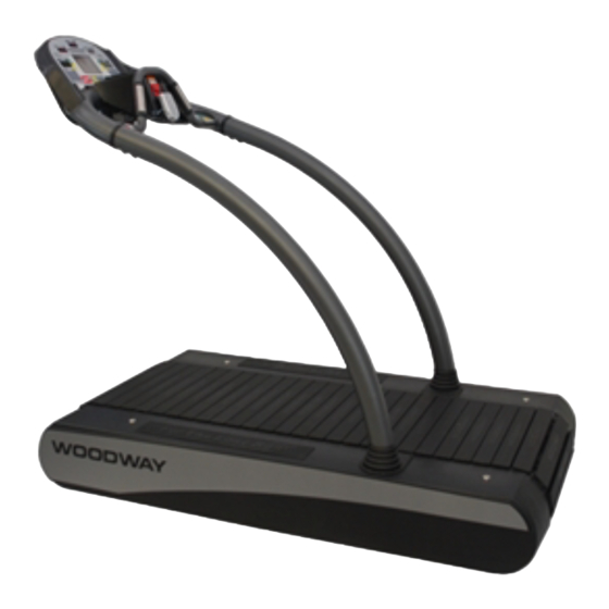
- Page 6 Fig. 24 Desmo assembly, removing side covers Insert wire and protective cover into the handrail tube to prevent damage during insertion. Fig. 25 Desmo assembly, wiring Prepare the mount for the tube. Fig. 26 Desmo assembly, tube mount 03/2016 – UM-MT-EN-01...
- Page 7 Fig. 27 Desmo assembly, inserting tubes Tighten the handrail mount bolts on both sides. Fig. 28 Desmo assembly, fixing the railing Remove electronic cover plate on the right side of the treadmill frame using a Phillips screw driver.
- Page 8 Lay the wire through the hole in the console. Fig. 30 Desmo assembly, connection 1 Attach the protective con- ductor (green) to the con- tact tab on the housing. Fig. 31 Desmo assembly, connection 2 Connect the display cable to the circuit board. The connector is J10.
- Page 9 12. Reinstall electronic cover plate on the right side of the treadmill frame using a Phillips screw driver. Fig. 34 Desmo assembly, electronic cover plate 13. Slide the side covers onto the left and right sides. 14. Guide the covers, slightly tilted under the handrail boots.
-
Page 10: Mercury, Path
The side covers must not be in contact with the running surface or drive belts on the rear left side! Fig. 36 Desmo assembly, adjusting side covers 6.4.4 Please contact your local representative for ELG assembly assistance. 6.4.5 Mercury, Path Tools required for assembly: ...
Need help?
Do you have a question about the DESMO and is the answer not in the manual?
Questions and answers