
Related Manuals for DeLonghi DE 60 E


Summary of Contents for DeLonghi DE 60 E
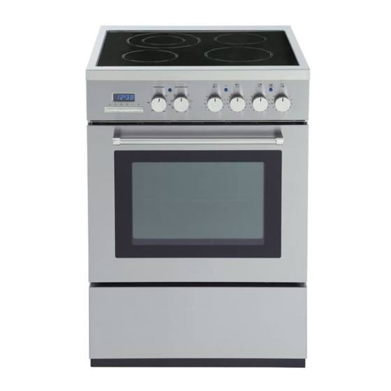
- Page 1 INSTALLATION and SERVICE INSTRUCTIONS USE and CARE INSTRUCTIONS DE 60 E CERAMIC COOKER distributed by DèLonghi Pty Ltd...
-
Page 2: Product Label
Dear Customer, Thank you for having purchased and given your preference to our product. The safety precautions and recommendations reported below are for your own safety and that of others. They will also provide a means by which to make full use of the features offered by your appliance. -
Page 3: Using The Oven For The First Time
USING THE OVEN FOR THE FIRST TIME You are advised to carry out the following operations: ■ Furnish the interior of the oven. ■ Switch the empty oven ON at maximum temperature for about two hours to eliminate traces of grease and smell from the components. ■... -
Page 4: Important Precautions And Recommendations
IMPORTANT PRECAUTIONS AND RECOMMENDATIONS After having unpacked the appliance, check to ensure that it is not damaged. In case of doubt, do not use it and consult your supplier or a professionally qualified technician. Packing elements (i.e. plastic bags, polystyrene foam, nails, packing straps, etc.) should not be left around within easy reach of children, as these may cause serious injuries. -
Page 5: Installation
INSTALLATION CAUTION: ■ This appliance must be installed in accordance with these installation instructions. ■ This appliance shall only be serviced by authorized personnel. ■ This appliance is to be installed only by an authorised person. ■ Incorrect installation, for which the manufacturer accepts no responsibility, may cause personal injury of damage. - Page 6 CONNECTING THE FEEDER CABLE Important! This cooker must be connected to the electricity supply only by an autho- rised person. To connect the feeder cable to the cooker it is necessary to: ■ Remove the screws that hold shield A behind the cooker (fig. 2). ■...
- Page 7 IMPORTANT – The appliance should be installed by a registered electrician in compliance with the current electrical regulations and in observation of the instructions supplied by the manufacturer. Failure to comply with this condition will render the guarantee invalid. – Always disconnect the cooker from mains power supply before carrying out any maintenance operations or repairs.
-
Page 8: Levelling The Cooker
LEVELLING THE COOKER The cooker is equipped with 4 levelling feet and may be levelled by screwing or unscrewing the feet with a spanner (fig. 6). It is important to observe the prescriptions of figures 4a, 4b. Figure 4a Figure 5 Figure 4b Supplied with the cooker in a separate kit... -
Page 9: Anti-Tilt Bracket
ANTI-TILT BRACKET Dotted line showing the position of the cooker when installed Important! To restrain the appliance and pre- vent it tipping accidentally, fit a bracket to its rear to fix it securely to the wall. Make sure you also fit the supplied lock pin to the anti-tilt bracket. -
Page 10: Use And Care
USE and CARE CAUTION: ■ This appliance must be used only for the task it has explicitly been designed for, that is for domestic cooking of foodstuffs. Any other form of usage is to be consid- ered as inappropriate and therefore dangerous. ■... -
Page 11: Grease Filter
■ To eliminate traces of grease in Figure 9 manufacture it is necessary to pre- heat the oven at the maximum tem- perature: • For 60 minutes in the posi- tion, for 30 minutes in the position and for another 15 min- utes in the position. - Page 12 TELESCOPIC SLIDING SHELF SUPPORTS The telescopic sliding shelf supports make it safer and easier to insert and remove the oven shelves and trays. They stop when they are pulled out to the maximum position. Important! When fitting the sliding shelf supports, make sure that you fit: ■...
- Page 13 To remove the telescopic sliding shelf supports: – Remove the side racks and the catalytic liners by unscrewing the fixing screws (Fig. 13). – Lay down the telescopic sliding shelf support and side racks, with the telescopic slid- ing shelf support underneath. –...
-
Page 14: Control Panel
CONTROL PANEL Figure 15 CONTROL PANEL - Controls description 1. Front right cooking zone control knob 2. Rear right cooking zone control knob 3. Rear left cooking zone control knob 4. Front left cooking zone control knob 5. Multifunction oven switch knob 6. -
Page 15: Cooking Zones
VITROCERAMIC HOB Figure 16 COOKING ZONES 1. Radiant hotplate Ø 145 1200 W 2. Radiant hotplate Ø 180 1800 W 3. Radiant hotplate Ø 145 1200 W 4. Double circuit radiant hotplate Ø 210/120 2100/700 W Attention: Detach the appliance from the mains if the ceramic hob is cracked and contact the After Sales Service. -
Page 16: How To Use The Vitroceramic Hob
HOW TO USE THE VITROCERAMIC HOB IMPORTANT NOTE: The heating elements incorporate a thermolimiter that switches the element ON/OFF during all settings to protect the ceramic glass from overheating. The use of incorrect pans and/or wrong pan positioning will cause the temperature limiter to operate more frequently, resulting in a reduction of cooking performance. - Page 17 DOUBLE RADIANT ZONE (fig. 20) The heating element is formed of a coil of resistant material which reaches the working temperature quickly. Operation of the cooking zone is controlled by a continuous energy regulator from 1 to 12 (maximum temperature) (fig. 19). To turn on both zones of the double element, turn the double element knob fully clockwise to the position To reduce the heat of the full double element, turn its knob anticlockwise to setting 12...
-
Page 18: Safety Hints
SAFETY HINTS: 1. Never put cooking foil or plastic materials on the ceramic surface when the hob is hot. 2. Make sure that the hob is clean before you use it. 3. Remember that the plates will remain hot for approximately half an hour after the plate has been switched off. -
Page 19: Residual Heat Indicator
Figure 23 RESIDUAL HEAT INDICATOR The hob also features a warning lamp (on the control panel fig. 23) which is wired to the plates. When the temperature of a cooking plate is over 60°C, the warning lamp is also lit-up to warn of heat on the sur- face of the hob. -
Page 20: Cooking Hints
Figure 24 Elements usage table COOKING HINTS: Knob Type of cooking setting Temperature control knob Switched OFF For melting operations (of butter or chocolate). To keep foods warm or heat small quantities of water. To heat greater quantities of water, and to reheat and simmer soups and stews. - Page 21 COOKWARE: It is very important that the pans used on the hobs are made of a suitable material and have the correct base as follows: ■ The base should be flat and smooth. ■ Any rough part on the pan base could scratch the hob surface. ■...
-
Page 22: Multifunction Oven
MULTIFUNCTION OVEN GENERAL FEATURES With the Multi-Function oven it is possible to cook a variety of food using the 6 different cooking functions. These 6 cooking functions are obtained using a combination of the 4 different heating elements plus a defrost function using the fan only. OPERATING PRINCIPLES Heating and cooking in the MULTI-FUNCTION oven are obtained in the following ways:... -
Page 23: Thermostat Knob
Figure 25 THERMOSTAT KNOB This only sets the cooking temperature and does not switch the oven on. Rotate clockwise until the required temperature is reached (from 50 °C to 250 °C). FUNCTION SELECTOR KNOB Rotate the knob clockwise to set the oven for one of the following functions. OVEN LIGHT By setting the knob to this position, only the oven light comes on. -
Page 24: Fan Forced
GRILLING The infrared grill element at the top of the oven comes on. The heat is dispersed by radiation. Use with the oven door closed and the thermostat knob to position between 50 °C and 200 °C max. For cooking hints, see the chapter “USE OF THE GRILL”. Ideal for: Intense grilling, browning, cooking au gratin and toasting etc. -
Page 25: Fan Grill
FAN GRILL Both the grill and the fan come on. Most of the cooking is done by grilling and then the hot air circulated around the oven. The oven door should be kept closed. The temperature can be set between 50 °C and 200 °C max. The oven should be preheated for 5 minutes before cooking. -
Page 26: Cooking Advice
COOKING ADVICE Remember to keep children away from the appliance when you use the grill or oven, since these parts become very hot. STERILIZATION Sterilization of foods to be preserved, in full and hermetically sealed jars, is done in the following way: a. -
Page 27: Grilling And Cooking Au Gratin
GRILLING AND COOKING AU GRATIN As the hot air completely covers the food to be cooked, grilling may be done with the food on the rack in the oven. The knob should be switched to position The thermostat should be set to 50 °C and 200 °C max and the oven pre- heated. - Page 28 RECOMMENDED COOKING TEMPERATURE Food °C °F Shelf Cooking Mark Position Time (approx) CAKES Victoria sandwich 2 or 3 20-25 mins Small cakes/buns 1 and 2 15-20 mins Maidera cake 2 or 3 20 mins 3 /4 Fruit cake hours 1 /2 Rich fruit cake 3 or 4 hours...
-
Page 29: Electronic Programmer
ELECTRONIC PROGRAMMER The electronic programmer is a device which groups together the following functions: ■ 24 hours clock with illuminated display ■ Timer (up to 23 hours and 59 minutes) ■ Program for automatic oven cooking (main oven only) ■ Program for semi-automatic oven cooking (main oven only) Description of the buttons: Automatic cooking taking place... -
Page 30: Electronic Clock
ELECTRONIC CLOCK ELECTRONIC TIMER (fig. 27) The programmer is equipped with an The timer programme consists only of a electronic clock with lighted numbers buzzer which may be set for a which indicate hours and minutes. maximum period of 23 hours and 59 Upon immediate connection of the minutes. -
Page 31: Automatic Oven Cooking
AUTOMATIC OVEN 3.Set the temperature and the cooking programme by using the switch and COOKING thermostat knobs of the oven (see To cook food automatically in the oven, specific chapters). it is necessary to: Now the oven is programmed and 1.Set the length of the cooking time everything will work automatically, that 2.Set the end of the cooking time... -
Page 32: Semi-Automatic Cooking
At the end of cooking, the oven and SEMI-AUTOMATIC symbol will turn off, the AUTO COOKING will flash and a buzzer will sound; that can be stopped by pushing any of the This is used to automatically switch off buttons. the oven after the desired cooking time has elapsed. -
Page 33: General Advice
Cleaning and Maintenance GENERAL ADVICE ■ Before you begin cleaning, you must ensure that the appliance is switched off. ■ It is advisable to clean when the appliance is cold and especially when cleaning the enamelled parts. ■ Avoid leaving alkaline or acidic substances (lemon juice, vinegar, etc.) on the surfaces. -
Page 34: Enamelled Parts
ENAMELLED PARTS All the enamelled parts must be cleaned with a sponge and soapy water only or other non-abrasive products. Dry preferably with a microfibre or soft cloth. STAINLESS STEEL SURFACES The stainless steel front panels on this cooker (facia, oven door, drawer) are protected by a finger-print proof lacquer. -
Page 35: Replacing The Oven Light
GRILL HEATING ELEMENT ■ The heating element is self-cleaning and does not require maintenance. The grill is secured to the rear wall of the oven on a hinge system that allows it to be lowered to allow proper access when cleaning the oven ceiling. GREASE FILTER Clean the filter after any cooking! The grease filter can be removed for cleaning and should be washed regularly in hot... -
Page 36: Storage Drawer
STORAGE DRAWER ■ The drawer comes out like a normal drawer. A safety catch stops it from sliding out. ■ The handle is concealed at bottom of front panel. ■ To remove the drawer proceed as per figure 38. ■ To replace the drawer repeat the steps in reverse order. -
Page 37: Removing The Oven Door
REMOVING THE OVEN Figure 39a DOOR The oven door can easily be removed as follows: – Open the door to the full extent (fig. 39a). – Open the lever A completely on the left and right hinges (fig. 39b). – Hold the door as shown in fig. 39. Figure 39b –... - Page 38 REMOVING THE INNER Figure 40 PANE OF GLASS To clean the inner pane of the oven door on both sides operate as follows: – Open the door to the full extent (fig. 40). – Open the lever A completely on the left and right hinges (fig.
- Page 39 REASSEMBLING THE INNER PANE Figure 45 To reassemble the inner pane of the oven door operate as follows: – Make sure the door is locked open (see Fig. 42). – Check the correct positioning of the no. 4 (four) silicon rubbers D (fig. 45). –...
-
Page 40: Wiring Diagram
WIRING DIAGRAM ELECTRIC DIAGRAM KEY Oven switch F2/3/5 Radiant hotplate energy regulators Double radiant hotplate energy regulator Oven programmer Oven lamp Oven thermostat Safety thermostat Thermal overload Top element Grill element Bottom element Circular element Residual heat lamp Cooling fan Thermostat pilot lamp Radiant hotplate pilot lamp P1/2/4... - Page 43 Descriptions and illustrations in this booklet are given as simply indicative. The manufacturer reserves the right, considering the characteristics of the models described here, at any time and without notice, to make eventual necessary modifications for their construction or for commercial needs.
- Page 44 cod. 1103196 ß3...
Need help?
Do you have a question about the DE 60 E and is the answer not in the manual?
Questions and answers
The oven wint go the clock light is flashing
The clock light on the DeLonghi DE 60 E oven is flashing because the timer is in operation, the cooking time has ended, or there is an error due to the time of day being between the calculated cooking start and end time. Additionally, a power cut can reset the clock and cancel set programs, causing the flashing.
To fix this issue, select a function using the respective button and set the required time within 5 seconds using the adjustment buttons. If the clock was reset due to a power cut, re-enter the correct time to restore normal operation.
This answer is automatically generated