
Related Manuals for DeLonghi DEF905EX1


Summary of Contents for DeLonghi DEF905EX1
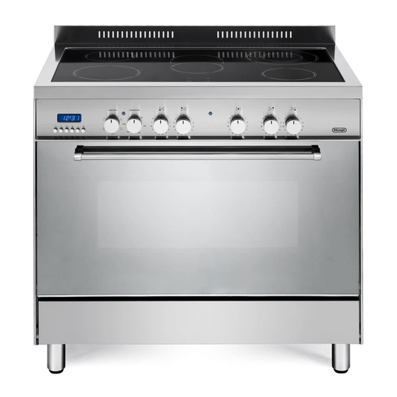
- Page 1 D E’ LO N G HI C OO KIN G INSTALLATION and SERVICE INSTRUCTIONS USE and CARE INSTRUCTIONS D EF9 05E X1 C E R A M I C CO O K ER distributed by DeLonghi Australia Pty Ltd DeLonghi New Zealand Ltd...
-
Page 2: Product Label
Dear Customer, Thank you for having purchased and given your preference to our product. The safety precautions and recommendations reported below are for your own safety and that of others. They will also provide a means by which to make full use of the features offered by your appliance. -
Page 3: Important Safety Precautions And Recommendations
IMPORTANT SAFETY PRECAUTIONS AND RECOMMENDATIONS IMPORTANT: This appliance is designed and manufactured solely for the cooking of domestic (household) food and is not suitable for any non domestic application and therefore should not be used in a commercial environment. The appliance guarantee will be void if the appliance is used within a non domestic environment i.e. - Page 4 ■ Do not use a steam cleaner because the moisture can get into the appliance therefore making it unsafe. ■ Do not touch the appliance with wet or damp hands (or feet). ■ Do not use the appliance whilst in bare feet ■...
- Page 5 ■ Make sure that electrical cables connecting other appliances in the proximity of the cooker cannot come into contact with the hob or become entrapped in the oven door. ■ WARNING: Unattended cooking on a hob with fat or oil can be dangerous and may result in fire.
- Page 6 ■ Do not line the oven walls or base with aluminium foil. Do not place baking trays or the drip tray on the base of the oven chamber. ■ FIRE RISK! Do not store flammable material in the oven or in the storage compartment.
-
Page 7: Installation
INSTALLATION CAUTION: ■ This appliance must be installed in accordance with these installation instructions. This appliance shall only be serviced by authorised personnel. ■ ■ This appliance is to be installed only by an authorised person in compliance with the current electrical regulations and in observation of the instructions supplied by the manufacturer. - Page 8 Cooker overall dimensions [mm] ■ height: min 900 - max 925 Figure 1 ■ width: 900 ■ depth: 600...
-
Page 9: Fitting The Adjustable Feet
FITTING THE ADJUSTABLE FEET The adjustable feet must be fitted to the base of the cooker before use (fig. 2). Rest the rear of the cooker on a piece of the polystyrene packaging exposing the base for the fitting of the feet. Fit the no. -
Page 10: Anti-Tilt Bracket
ANTI-TILT BRACKET Figure 8 Important! To restrain the appliance and prevent it tipping accidentally, fit a bracket to its rear to fix it securely to the wall. Make + 25 sure you also fit the supplied lock pin to the anti-tilt bracket. + 25 To fit the anti-tilt bracket: After you have located where the... -
Page 11: Electrical Requirements
ELECTRICAL REQUIREMENTS ■ The appliance must be connected to the mains checking that the voltage corresponds to the value given in the rating plate and that the electrical cable sections can withstand the load specified on the plate. ■ A suitable disconnection switch must be incorporated in the permanent wiring, mounted and positioned to comply with the local wiring rules and regulations. -
Page 12: Electric Connection
LOCATING THE AREA FOR ELECTRICAL CONNECTION ELECTRIC CONNECTION Dotted line showing the position of the cooker when installed Area for ELECTRIC connection Figure 11... -
Page 13: Connection Of The Power Supply Cable
CONNECTION OF THE POWER SUPPLY CABLE Important! This cooker must be connected to the electricity supply only by an authorised person. To connect the feeder cable to the cooker it is necessary to: • Remove the two screws that hold shield “A” behind the cooker (fig. 12). •... - Page 14 Figure 12 Figure 13 230 V~ 230 V~, 240 V~ 1 2 3 4 5 N (L 230 V 3~ 230 V 3~, 240 V 3~ 1 2 3 4 5 230 V~ 230 V 3~ 230 V~, 240 V~ 230 V 3~, 240 V 3~ 400 V 3N~ 400 V 3N~, 415 V 3N~...
-
Page 15: Electric Diagram
ELECTRIC DIAGRAM Figure 15... - Page 16 ELECTRIC DIAGRAM KEY P1/2/5 Hob single zones elements Hob double zone (oval) element Hob double zone element F2/3/6 Energy regulators (single zones) F4/5 Energy regulators (double zones) Oven switch Oven thermostat Oven lamp Oven programmer Cooling fan motor Oven fan motor Oven top element Oven grill element Oven bottom element...
-
Page 17: Using The Oven For The First Time
USE AND CARE CAUTION: ■ This appliance must be used only for the task it has explicitly been designed for, that is for domestic cooking of foodstuffs. Any other form of usage is to be considered as inappropriate and therefore dangerous. ■... - Page 18 GREASE FILTER (OPTIONAL COMPONENT, CAN BE PURCHASED SEPARATELY) ■ A special screen can be fitted at the back of the oven to catch grease particles, mainly when meat is being roasted. Slide in the grease filter on the back of the oven as in fig. 19. ■...
-
Page 19: Control Panel
CONTROL PANEL Figure 20 Controls description Front right cooking zone control knob Rear right cooking zone control knob Central cooking zone control knob Rear left cooking zone control knob Front left cooking zone control knob Oven temperature control knob Oven function selector control knob Electronic programmer Pilot lamps: Cooking zone/s ON indicator light... - Page 20 VITROCERAMIC HOB Figure 21 VITROCERAMIC COOKING HOB “Hi-Light” single zone, Ø 180 mm 1800 W “Hi-Light” single zone, Ø 145 mm 1200 W “Hi-Light” double zone (oval), Ø 145 x 250 mm 2000/1100 W “Hi-Light” double zone, Ø 210/120 mm 2200/750 W “Hi-Light”...
-
Page 21: How To Use The Vitroceramic Hob
HOW TO USE THE VITROCERAMIC HOB The ceramic surface of the hob allows a fast transmission of heat in the vertical direction, from the heating elements underneath the ceramic glass to the pans set on it. The heat does not spread in a horizontal direction, so that the glass stays “cool” at only a few centimeters from the cooking plate. -
Page 22: Double Zone
“HI-LIGHT” DOUBLE ZONES (figs. 25, 26) ■ The heating element is formed of 2 coils of resistant material which reaches the working temperature quickly. ■ This zone is controlled by a continuous energy regulator switch (fig. 24). The heat intensity can be regulated continuously from “0” to “12” (max). ■... -
Page 23: Safety Hints
SAFETY HINTS Never put cooking foil or plastic materials on the ceramic surface when the hob is hot. Make sure that the hob is clean before you use it. Always ensure that the base of your saucepan is clean and dry before placing on the hob. - Page 24 RESIDUAL HEAT INDICATORS Figure 29 The hob also features no. 6 (six) warning lights which connected corresponding plates. When the temperature of a cooking plate is above 60°C, the relevant warning light will also light up to warn of heat on the surface of the hob.
-
Page 25: Cooking Hints
Figure 30 Elements usage table Knob TYPE OF COOKING setting COOKING HINTS: Switched OFF Temperature control knob melting operations (butter, chocolate). To maintain food hot and to heat small quantities of liquid (sauces, eggs). To heat bigger quantities; to whip creams and sauces (vegetables, fruits, soups). - Page 26 COOKWARE: It is very important that the pans used on the hobs are made of a suitable material and have the correct base as follows: ■ The base should be flat and smooth. ■ Any rough part on the pan base could scratch the hob surface. ■...
-
Page 27: General Features
COOKING WITH FAN ASSISTED OVEN OPERATING PRINCIPLES Attention: The oven door becomes Heating and cooking in the fan assisted very hot during operation. oven are obtained in the following ways: Keep children away. by normal convection The heat is produced by the upper and lower heating elements. -
Page 28: Thermostat Knob
Figure 31 Figure 32 THERMOSTAT KNOB (fig. 32) To turn on the heating elements of the oven, set the function selector knob on the desired program and the thermostat knob onto the desired temperature. To set the temperature, it is necessary to make the knob indicator meet the chosen number. The elements will turn ON or OFF automatically according to the energy need which is determined by the thermostat. -
Page 29: Defrosting Frozen Foods
CONVECTION COOKING WITH VENTILATION The upper and lower heating elements and the fan turn on. The heat coming from the top and bottom is diffused by forced convection. The temperature must be regulated between 50°C and the maximum temperature with the thermostat knob. -
Page 30: Cooking Advice
COOKING ADVICE The external parts of the appliance STERILIZATION become hot during operation. Sterilization of foods to be conserved, in Keep children well out of reach. full and hermetically sealed jars, is done in the following way: Set the switch to position OVEN COOKING Set the thermostat knob to position 185°C and preheat the oven. -
Page 31: Use Of The Grill
USE OF THE GRILL Preheat the oven for about 5 minutes. Introduce the food to be cooked, positioning the rack as close to the grill as possible. The dripping pan should be placed under the rack to catch the cooking juices and fats. - Page 32 RECOMMENDED COOKING TEMPERATURE Shelf Cooking Food °C °F Mark Position* Time (approx) CAKES Victoria sandwich 2 or 3 20-25 mins Small cakes/buns 1 and 2 15-20 mins Maidera cake 2 or 3 20 mins Fruit cake hours Rich fruit cake 3 or 4 hours Scones...
- Page 33 DIGITAL ELECTRONIC PROGRAMMER The electronic programmer is a device which groups together the following functions: ■ 24 hours clock with illuminated display. ■ Timer (up to 23 hours and 59 minutes). ■ Program for automatic oven cooking. ■ Program for semi-automatic oven cooking. Description illuminated Description of the buttons:...
-
Page 34: Electronic Timer
ELECTRONIC CLOCK ELECTRONIC TIMER (fig. 34) The programmer is equipped with an The timer program consists only of a electronic clock with illuminated numbers buzzer which may be set for a maximum which indicates hours and minutes. period of 23 hours and 59 minutes. Upon immediate connection of the oven or If the AUTO symbol is flashing push the after a power cut, three zeros will flash on... -
Page 35: Automatic Oven Cooking
AUTOMATIC OVEN COOKING Set the temperature and the cooking program by using the switch and To cook food automatically in the oven, it is thermostat knobs of the oven (see necessary to: specific chapters). Set the length of the cooking period. oven programmed Set the end of the cooking time. -
Page 36: Semi-Automatic Cooking
SEMI-AUTOMATIC COOKING At the end of the cooking time the oven will turn off automatically, the symbol will This is used to automatically switch off the turn off, AUTO will flash and a buzzer will oven after the desired cooking time has sound, which can be turned off by pushing elapsed. -
Page 37: Cleaning And Maintenance
CLEANING AND MAINTENANCE GENERAL ADVICE ■ Before you begin cleaning, you must ensure that the appliance is switched off and disconnected from the electrical power supply. ■ It is advisable to clean when the appliance is cold and especially when cleaning the enamelled parts. -
Page 38: Cleaning The Ceramic Hob
CLEANING THE CERAMIC HOB Figure 41 ■ Remove spillages and other types of incrustations. ■ Dust or food particles can be removed with a damp cloth. ■ If you use a detergent, please make sure that it is not abrasive or scouring. Abrasive or scouring powders can damage the glass surface of the hob. -
Page 39: Storage Compartment
GRILL HEATING ELEMENT ■ The heating element is self-cleaning and does not require maintenance. Figure 42 OVEN FLOOR The oven floor “F” (fig. 42) can be easily removed to facilitate cleaning. Remember replace floor correctly afterwards. Be careful not to confuse the tray “L” with the oven floor “F”. - Page 40 STORAGE COMPARTMENT The storage compartment is accessible through the pivoting panel (fig. 45). Do not store flammable material in the storage compartment. Figure 45 REMOVING AND REPLACING THE INNER DOOR GLASS PANE FOR CLEANING If you wish to clean the inner glass of the door, make sure you follow the precautions and instructions very carefully.
-
Page 41: Removing The Oven Door
REMOVING THE OVEN DOOR Figure 47a The oven door can easily be removed as follows: ■ Open the door to the full extent (fig. 47a). ■ Open the lever “A” completely on the left and right hinges (fig. 47b). ■ Hold the door as shown in fig. - Page 42 REFIT THE DOOR Figure 48a ■ Hold the door firmly (fig. 48a). ■ Insert the hinge tongues into the slots, making sure that the groove drops into place as shown in the figure 48b. ■ Open the door to its full extent. ■...
-
Page 43: Service And Maintenance
Oven only: none semi-automatic or automatic cooking program has been selected. Both the fuse and the mains fuse are intact. Should you still require assistance please contact our Customer Service Centre for your nearest Authorised Delonghi Service Agent. - Page 44 .au ww w.de lo nghi.co .nz...
Need help?
Do you have a question about the DEF905EX1 and is the answer not in the manual?
Questions and answers