
Related Manuals for DeLonghi DSR 927 DFX


Summary of Contents for DeLonghi DSR 927 DFX
- Page 1 D E’ LO N G H I C OO KIN G USER & INSTALLATION INSTRUCTIONS D S R 92 7 DF X DUAL FUEL COOKER...
-
Page 2: Table Of Contents
CONTENTS Page Number Introduction ..........Important Safety Precautions &... -
Page 3: Introduction
Dear Customer, Thank you for purchasing the DeLonghi DSR 927-GX gas cooker. The safety precautions and recommendations listed below are for your own safety and that of others. They will also provide a means by which to make full use of the features offered by your appliance. -
Page 4: Important Safety Precautions & Recommendations
IMPORTANT SAFETY PRECAUTIONS AND RECOMMENDATIONS IMPORTANT: This appliance is designed and manufactured solely for the cooking of domestic (household) food and is not suitable for any non domestic application and therefore should not be used in a commercial environment. The appliance guarantee will be void if the appliance is used within a non domestic environment i.e. - Page 5 • Do not attempt to modify the technical characteristics of the appliance as this may become dangerous to use. The manufacturer declines all responsibility for any inconvenience resulting from the inobservance of this condition. • CAUTION: this appIiance must only be installed in a permanently ventilated room in compliance with the applicable regulations.
- Page 6 • The manufacturer declines all liability for injury to persons or damage to property caused by incorrect or improper use of the appliance. • WARNING: During use the appliance and its accessible parts become hot; they remain hot for some time after use. –...
- Page 7 • CAUTION: Do not use harsh abrasive cleaners or sharp metal scrapers to clean the oven door glass since they can scratch the surface, which may result in shattering of the glass. • Do not line the oven walls or base with aluminium foil. Do not place baking trays or the drip tray on the base of the oven chamber.
- Page 8 ENERGY LABELLING/ECODESIGN • Commission delegated regulation (EU) No 65/2014 (supplementing Directive 2010/30/EU of the European Parliament and of the Council). • Commission regulation (EU) No 66/2014 (implementing Directive 2009/125/EC of the European Parliament and of the Council). Reference to the measurement and calculation methods used to establish compliance with the above requirements: •...
-
Page 9: Advice For The Installer
Advice for the installer IMPORTANT • Cooker installation must only be carried out by QUALIFIED TECHNICIANS and in compliance with local safety standards. Failure to install the appliance correctly could invalidate any manufacturer’s warranty. • The appliance must be installed in compliance with regulations in force in your country and in observation of the manufacturer’s instructions. -
Page 10: Installation
INSTALLATION INSTALLATION This cooker has class “2/1” overheating protection so that it can be installed next to a cabinet. If the cooker is installed adjacent to furniture which is higher than the gas hob cooktop, a gap of at least 200 mm must be left between the side of the cooker and the furniture. The walls and kitchen furniture surrounding the appliance must be made of non-flammable material. - Page 11 FITTING THE ADJUSTABLE FEET The adjustable feet must be fitted to the base of the cooker before use (fig. 1.2). Rest the rear of the cooker on a piece of the polystyrene packaging exposing the base for the fitting of the feet. Fit the 4 legs by screwing them tight into the support base as shown in figure 1.3.
- Page 12 MOVING THE COOKER WARNING: When raising cooker to upright position always ensure two people carry out this manoeuvre to prevent damage to the adjustable feet (fig. 1.6). Fig. 1.6 WARNING WARNING When moving cooker to its final position Be carefull: do not lift the cooker by the DO NOT DRAG (fig.
- Page 13 ANTI-TILT BRACKET Important! To restrain the appliance and prevent it tipping accidentally, fit a bracket to its rear to fix it securely to the wall. To fit the anti-tilt bracket: After you have located where the cooker is to be positioned, mark on the wall the place where the two screws of the anti-tilt bracket have to be fitted.
- Page 14 PROVISION FOR VENTILATION • The appliance should be installed into a room or space with an air supply in accordan- ce with the current version of BS 5440-2: 2000. • For rooms with a volume of less than 5m - permanent ventilation of 100 cm free area must be provided.
-
Page 15: Gas Section
GAS SECTION GAS INSTALLATION REQUIREMENTS Important ! • The walls adjacent to the cooker must be of heat-resistant material. • Before installation, make sure that the local distribution conditions (gas type and pressure) and the adjustment of this appliance are compatible. The appliance adjustment conditions are given on the plate or the label. - Page 16 GAS CONNECTION Cat: 2H 3+ It is a requirement that a restraining chain (not supplied with the appliance) is also used to prevent stress being applied to the gas hose or pipework. The chain should be attached securely to the product and on the wall (fig. 2.1). RESTRAINING CHAIN Fig.
- Page 17 Notes: • Flexible hoses can be used where the sited ambient temperature of the hose does not exceed 70°C. These hoses must be manufactured in accordance with BS669 part 1 or EN 14800 and be of the correct construction for the type of gas being used.
- Page 18 Fig. 2.3 Cooker manifold (gas inlet pipe) Manifold male pipe fitting 1/2” G cylindrical (ISO 228-1) male Fibre washer ( * ) 1/2” G cylindrical (ISO 228-1) female Connector ( * ) 1/2” BSP female Supplied with the appliance in a separate kit IMPORTANT PRESCRIPTIONS FOR GAS CONNECTION Rear wall...
- Page 19 GAS MAINTENANCE TABLE FOR THE CHOICE OF THE INJECTORS - Cat. 2H 3+ Natural Gas G30 28-30 mbar G20 20 mbar Nominal Reduced G31 37 mbar power power BURNERS Ring Ring [kW] [kW] Ø injector Ø injector opening opening [1/100 mm] [1/100 mm] [mm] [mm]...
- Page 20 REPLACEMENT Semi-rapid burners INJECTORS OF THE BURNERS Select the injectors to be replaced according to the “Table for the choice of the injectors”. nozzle diameters, expressed hundredths of a millimetre, are marked on the body of each injector. If the injectors are not supplied they can be obtained from the “Service Centre”.
- Page 21 SETTING THE MINIMUM OF THE COOKTOP BURNERS When switching from one type of gas to another, the minimum flow rate must also be correct: the flame should not go out even when passing suddenly from maximum to minimum flame. To regulate the flame follow the instructions below: Fig.
- Page 22 ELECTRICAL SECTION IMPORTANT: The appliance must be installed in accordance with the manufactu- rer’s instructions. Incorrect installation, for which the manufacturer accepts no re- sponsibility, may cause damage to persons, animals and property. The connection of the appliance to earth is mandatory. The manufacturer declines all responsibility for any inconvenience resulting from the inobservance of this condition.
- Page 23 CONNECTION OF THE POWER SUPPLY CABLE WARNING: If the power supply cable is damaged, it must be replaced only by an authorised service agent in order to avoid a hazard. • Unhook the terminal board cover by inserting a screwdriver into the two hooks “A” (fig. 3.1). •...
-
Page 24: Advice For The User
Advice for the user... -
Page 25: Cooking Hob
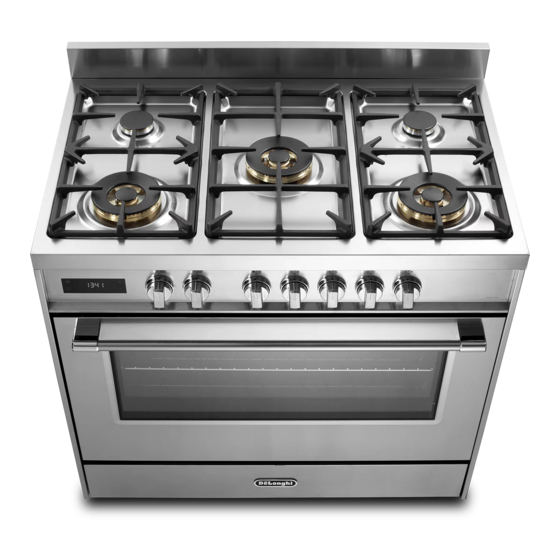
COOKING HOB Fig. 1.1 GAS BURNERS Auxiliary burner (A) 1,00 kW Semi-rapid burner (SR) 1,75 kW Triple ring burner (TC) 4,00 kW Dual burner (D) 4,00 kW Notes: • The electric ignition is incorporated in the knobs. • The appliance has a safety valve system fitted, the flow of gas will be stopped if and when the flame should accidentally go out. -
Page 26: Control Panel
CONTROL PANEL Fig. 2.1 CONTROLS DESCRIPTION Front right burner control knob Rear right burner control knob Central burner control knob Rear left burner control knob Front left burner control knob Multifunction oven thermostat control knob Multifunction oven selector control knob Electronic clock/programmer “Touch-control”... -
Page 27: Use Of The Hob Burners
USE OF THE HOB BURNERS GAS BURNERS (Semi-rapid and triple ring burners) Gas flow to the burners is adjusted by turning the knobs (illustrated in fig. 3.1) which control the valves. Turning the knob so that the symbols printed on itself point to the symbol printed on the control panel achieves the following functions: Knob Function... - Page 28 LIGHTING GAS BURNERS FITTED WITH SAFETY VALVE DEVICE (Semi-rapid and triple ring burners) In order to light the burner, you must: Push and turn the knob in an anticlockwise direction up to the position (maximum rate), push in and hold the knob until the flame has been lit (fig.
- Page 29 GAS BURNERS (Dual) The Dual Burner is a very flexible burner which allows different regulations and optimal cooking. It is composed by one inner and one outer crown; the flame of the inner crown can be regulated separately from the flames of the outer crown. The Dual Burner can be used: •...
- Page 30 LIGHTING GAS BURNERS FITTED WITH SAFETY VALVE DEVICE (Dual burner) In order to light the burner, you must: Push and turn the knob in an anti- clockwise direction up to the position (maximum rate of inner + outer crown); push in and hold the knob until the flame has been lit (fig.
- Page 31 CHOICE OF THE BURNER On the control panel, near every knob there is a diagram that indicates which burner is controlled by that knob. The suitable burner must be chosen according to the diameter and the capacity used. The burners and pans must be used in accordance with the following instructions: DIAMETERS OF PANS WHICH MAY BE USED ON THE BURNERS BURNERS MINIMUM...
- Page 32 WOK STAND (OPTIONAL) Only flat bottom pans of the correct size are to be placed on the pan support above the Triple-ring or Dual burner. When using a WOK, the supplied wok stand must be placed onto the pan stand to avoid any faulty operation of the triple-ring or Dual burner (fig.
-
Page 33: Multifunction Oven
MULTIFUNCTION OVEN OPERATING PRINCIPLES Attention: The oven door becomes Heating cooking very hot during operation. MULTIFUNCTION oven are obtained in the Keep children away. following ways: by normal convection The heat is produced by the upper and GENERAL FEATURES lower heating elements. As its name indicates, this is an oven by forced convection that presents particular features from an... - Page 34 Fig. 4.1 Fig. 4.2 TEMPERATURE KNOB (fig. 4.2) To turn on the heating elements of the oven, set first the function selector to the required setting and then the thermostat knob to the desired temperature. To set the temperature, line up the temperature knob indicator with the required temperature.
- Page 35 LOWER HEATING ELEMENT In this position only the lower heating element is switched on. Heat is distributed by natural convection. The temperature must be regulated between 40°C and 225°C maximum. Recommended for: To complete cooking of dishes that require higher temperature at the bottom. CONVECTION COOKING WITH VENTILATION - PIZZA The upper and lower heating elements and the fan turn on.
- Page 36 VENTILATED GRILL COOKING The infra-red ray grill and the fan are on. The heat is mainly diffused by radiation and the fan then distributes it throughout the oven. The temperature must be regulated between 40°C and 225°C for max 30 minutes, with the thermostat knob. It is necessary to preheat the oven for about 5 minutes.
- Page 37 ROTISSERIE USE OF THE ROTISSERIE (fig. 4.3) This is used for spit roasting under the grill • Insert the tray into the lowest rack and comprises: holders of the oven and insert the rod support into the intermediate rack • an electric motor fitted to the rear of holders.
-
Page 38: Oven Temperature Guide
OVEN TEMPERATURE GUIDE Electric oven temperature Cooking process Oven heat Gas mark °C °F Keeping food hot, very cool ½ milk puddings Egg custards cool Rich fruit cakes, cool braising Low temperature moderate roasting, shortbread Victoria sandwich, plain fruit cake, moderate baked fish Small cakes, choux... -
Page 39: Elettronic Clocl "Touch-Control
ELETTRONIC CLOCK “TOUCH-CONTROL” 10 9 8 7 6 2 3 4 Description of display symbols: Oven on Cooking time End of cooking time Timer Oven temperature AM/PM time format Screen brightness Acoustic signal volume Time of day setting 10. Programmer ‘touch’ control panel key lock Description of the ‘touch control’... - Page 40 “TOUCH-CONTROL” KEYS The “touch-control” keys shall be operated by the fingers (just by touching the key). When using touch controls it is best to use the ball of your finger rather than the tip. Program and menu selection: after starting the procedure, the selection is automatically deactivated after approx.
- Page 41 SEMI-AUTOMATIC COOKING This is used to automatically switch off the oven after the desired cooking time has elapsed. Check the clock shows the correct time. The semi-automatic cooking program can be set for a maximum period of 10 hours. Select the function and temperature (function and temperature knobs). The oven will come on.
- Page 42 To cancel the automatic cooking program at any time, proceed as described in the “SEMI- AUTOMATIC COOKING” chapter. Turn the temperature and function knobs to the off position, otherwise continue cooking and then remember to turn the oven off manually. ATTENTION - VERY IMPORTANT (AUTOMATIC OR SEMI-AUTOMATIC COOKING): If a very short power interruption occurs, the oven keeps the programming.
- Page 43 SCREEN BRIGHTNESS SETTING It is possible to select three brightness levels. • Touch the " " key for more than 2 seconds, then touch the same key several times until the " " symbol flashes. • Touch the “+” or “―”; key; the display shows the brightness set (“d-01”, “d-02” or “d-03”).
-
Page 44: Cleaning & Maintenance
CLEANING AND MAINTENANCE GENERAL ADVICE CLEANING • Before begin cleaning, Stainless steel hob: Spillage on • must ensure that the appliance is the hob can usually be removed by disconnected from the electrical power a damp soapy cloth. More obstinate supply. - Page 45 would recommend the whole area is cleaned. NOTE: Please ensure the slots/castlellations are kept free of any material/cleaner. DO NOT PUT BURNER BODIES INTO A DISHWASHER AS THIS MAY TURN THEM BLACK. • Inside of oven: The oven should always be cleaned after use when it has cooled down.
- Page 46 GAS TAPS Do not let cleaning products come into contact with the valves. Periodic lubrication of the gas taps must be carried out by specialist personnel only. In the event of operating faults in the gas taps, call the Service Department. INSIDE OF OVEN The oven should always be cleaned after use when it has cooled down.
- Page 47 Fig. 6.1 Fig. 6.2 TRIPLE-RING BURNER Fig. 6.3...
- Page 48 DUAL BURNER Fig. 6.4 Fig. 6.5 Fig. 6.6...
- Page 49 OVEN FITTING OUT • Assemble the wire racks to the oven walls using the 2 screws (fig. 6.7a). In the models with catalytic panels supplied, interpose the catalytic panels “A” with the arrow up (fig. 6.7a). • Slide the rack into the runners (fig. 6.7b). The rack must be fitted so that the safety notch, which stops it sliding out, faces the inside of the oven;...
- Page 50 REPLACING THE OVEN LIGHTS WARNING: Ensure the appliance is switched off before replacing the lamp to avoid the possibility of electric shock. WRONG • Let the oven cavity and the heating elements cool down. • Switch off the electrical supply. •...
- Page 51 TELESCOPIC SLIDING SHELF SUPPORTS The telescopic sliding shelf supports make it safer and easier to insert and remove the oven shelves and trays. They stop when they are pulled out to the maximum position. Important! When fitting the sliding shelf supports, make sure that you fit: •...
- Page 52 REMOVING AND REPLACING THE INNER DOOR GLASS PANE FOR CLEANING If you wish to clean the inner glass of the door, make sure you follow the precautions and instructions very carefully. Replacing the glass pane and the door incorrectly may result in damage to the appliance and may void your warranty.
- Page 53 REMOVING THE OVEN DOOR The oven door can easily be removed as follows: • Open the door to the full extent (fig. 6.11). • Open the lever “A” completely on the left and right hinges (fig. 6.12). • Hold the door as shown in fig. 6.13. Fig.
- Page 54 REFIT THE DOOR Hold the door firmly (fig. 6.16). Insert the hinge tongues into the slots, making sure that the groove drops into place as shown in the figure 6.17. Open the door to its full extent. Fully close the levers “A” on the left and right hinges, as shown in the figure 6.18. Close the door and check that it is properly in place.
- Page 55 CLEANING AND MAINTENANCE Your new “De’Longhi” product comes with 12-month guarantee covering all parts and labour. If your appliance proves to be defective as a result of faulty materials or workmanship during the guarantee period, these parts will be repaired or replaced free of charge. AFTER SALES SERVICE Should you require service, spares or product information and advice: •...
- Page 56 De scri pt io n s a n d il lu st ra tio ns in th is b o ok let ar e g iv en a s simply indicati ve. Th e m an u fa ctu rer re se rv es th e r igh t,...
Need help?
Do you have a question about the DSR 927 DFX and is the answer not in the manual?
Questions and answers