ONEAC ON Series User Instruction Manual
Hide thumbs
Also See for ON Series:
- User instruction manual (32 pages) ,
- User instruction manual (31 pages) ,
- Instruction manual (26 pages)
Table of Contents
Advertisement
ON Series
IMPORTANT SAFETY INSTRUCTIONS
SAVE THESE INSTRUCTIONS.
Please read and save these instructions. This manual contains important
instructions for the ON Series UPS family. Follow these instructions during the
unpacking, installation and maintenance of the UPS and batteries. If you have a
problem with the UPS, please refer to this manual before calling the Technical
Support Department. The Troubleshooting section on page 61 addresses most
UPS-related issues.
Licenses and Trademarks
ONEAC, ON Series, Virtual Kelvin Ground, Environmental Reference Ground
and MopUPS are all registered trade marks and ChangeUPS, ONBoost, and
ONEP
, are trademarks of ONEAC Corporation. All other trademarks, product
LUS
and corporate names are the property of their respective owners.
ONEAC USA
27944 North Bradley Road
Libertyville, IL 60048-9700
USA
Telephone: (847) 816-6000
Toll Free: (800) 327-8801
Facsimile: (847) 680-5124
Entire contents copyright © 2000 ONEAC Corporation. All rights reserved. Reproduction in whole or
in part without permission is prohibited. All information subject to change without notice.
913-300-1 Rev. E
ON Series User Instruction Manual
ON Series User Instruction Manual
User Instruction Manual
®
ONEAC EUROPE
18 & 20 Blacklands Way
Abingdon Business Park
Abingdon, Oxfordshire OX14 1DY
United Kingdom
Telephone: +44 (0) 1235 534721
Facsimile: +44 (0) 1235 534197
4/00
Advertisement
Table of Contents
Troubleshooting

Related Manuals for ONEAC ON Series


Summary of Contents for ONEAC ON Series
-
Page 1: Important Safety Instructions
Toll Free: (800) 327-8801 Facsimile: +44 (0) 1235 534197 Facsimile: (847) 680-5124 Entire contents copyright © 2000 ONEAC Corporation. All rights reserved. Reproduction in whole or in part without permission is prohibited. All information subject to change without notice. 913-300-1 Rev. E... -
Page 2: Table Of Contents
Contents Contents Introduction ..................1 Registering Your ONEAC UPS ............. 1 Technical Support ................1 FCC Compliance ................2 Safety ....................3 (English) ..................3 Sicherheitshinweise ................4 (Deutsch) ..................4 Mesures de sécurité ................5 (Français) ..................5 Seguridad ................... 6 (Español) .................. - Page 3 Units ..................66 Batteries ..................66 Limitations of Warranty ..............66 Exclusive Remedies ..............66 Return Procedure ...............66 Appendix A: Accessories Interface Capabilities ........67 Appendix B: Operating in Power Environments Below 110V Nominal 68 Appendix C: Accessing Remote Off ...........70 ON Series User Instruction Manual...
-
Page 4: Introduction
We take pride in every unit that leaves our manufacturing facility. Registering To ensure that your ON Series model and serial number are registered, complete and mail the Your ONEAC enclosed postage-paid warranty card. Technical ONEAC offers 24-hour technical support. -
Page 5: Fcc Compliance
ATTENTION: Operation of this equipment in a residential area may cause harmful radio communications interference. The user is responsible for correcting the interference. ON Series User Instruction Manual... -
Page 6: Safety
UPS may be lethal. Internal components are powered even when the power switch is in the OFF position. Even with the battery disconnected and the unit unplugged, energy is stored in high voltage capacitors and represents a severe shock hazard. ON Series User Instruction Manual... -
Page 7: Sicherheitshinweise
Komponenten führen Strom, selbst wenn der Stromschalter auf AUS (OFF) steht. Auch wenn die Batterie nicht angeschlossen und der Stecker des Gerätes ausgesteckt ist, wird Energie in Hochspannungskondensatoren gespeichert, und dies bedeutet eine ernsthafte Elektroschockgefahr. ON Series User Instruction Manual... -
Page 8: Mesures De Sécurité
ARRÊT (OFF). Même lorsque la batterie est déconnectée et l'unité débranchée, de l'énergie est stockée dans des condensateurs à haute tension et représente un grave risque d'électrocution. ON Series User Instruction Manual... -
Page 9: Seguridad
APAGADO (OFF). Incluso si la batería está desconectada y la unidad desenchufada, se almacena energía en capacitores de alto voltaje, lo cual representa un peligro grave de descarga. ON Series User Instruction Manual... -
Page 10: Theory Of Operation
Theory of Operation Theory of The ON Series UPS has two operating modes: Conditioned AC Power and Conditioned Battery Operation Backup. AC Power Mode When AC utility power is present and within the correct voltage range, the UPS provides fully conditioned power: •... - Page 11 The UPS monitors the line and provides output when utility power is restored to normal operating range. ON Series UPS: Block Diagram of Architecture Output Control Load...
-
Page 12: Inrush Tolerance
“c9”. To reset, turn the UPS OFF, remove some of the load, then turn the UPS ON. (For GS compliance: The power distribution system for all models is type TN.) ON Series User Instruction Manual... - Page 13 ON. • If the circuit breaker trips with nothing plugged into the output receptacles, there may be an internal problem with the UPS. Call ONEAC Technical Support for assistance (refer to page 1).
-
Page 14: Setup And Installation
Inspection and Previous experience with UPS operation is not Unpacking required prior to operating ON Series units. Before shipment, this product was tested, inspected, and found to be free of mechanical and electrical defects. Upon receipt of your UPS, carefully examine the packing containers for any sign of physical damage. -
Page 15: Environmental Reference Ground
For use, remove the green screw on the back panel, attach a ground cord connector, and reinstall the screw. Interface Connector DIP Switches Auxiliary Output Interface Receptacles Port IEC Input Connector Circuit Breaker Environmental Reference Ground Model Shown: ON900A-SN ON Series User Instruction Manual... -
Page 16: Setup Precaution
ATTENTION: The UPS should not be stored at temperatures below -15 ° C (+5 ° F). Ventilation The ventilation requirement for standard ON Series UPSs is 2 in. (50 mm) minimum clearance on all sides. Rackmount units are vented at the front and back. -
Page 17: Grounding The Unit
NOTE: The ON2000A requires a 20 Amp circuit and receptacle for power. 15 A 20 A NOTE: When connecting the UPS, make sure that the receptacle has power available and is not controlled by a wall switch. ON Series User Instruction Manual... -
Page 18: Installing Standard On2000 Units
Connect the battery power cable as shown below. Secure the cable with screws (supplied) at each side flange. Interface DIP Switches Connector Output Receptacles Auxiliary Battery Power Interface Cable Port Circuit Breaker AC Line Cord Receptacle Ground ON2000 (Standard Model) ON Series User Instruction Manual... -
Page 19: Installing On2200Xa Extended Runtime Units
220 – 240 volts rms. Remove the front cover of the power unit and set the input voltage toggle switch to the position that matches the feed voltage. Replace the cover. Input Voltage Selection Switch ON Series User Instruction Manual... -
Page 20: Installing Standard Extended Runtime Units
If the connection is incorrect or incomplete, runtime reporting and assessment of the batteries will be inaccurate. For CE compliance, add wire between chassis of power unit and chassis (earth) of battery cabinet(s). ON Series User Instruction Manual... - Page 21 UPS and then to a properly grounded AC wall receptacle. 4. Connect the battery unit’s power cable to the main unit. Secure the cable with screws (supplied) at each side flange. The battery unit’s power input is not used. ON Series User Instruction Manual...
- Page 22 7. Connect the next battery unit’s power cable to the closest battery unit’s power input. Secure the cable with screws (supplied). Continue this process until power cables connect all battery units in a “chain”. The last battery unit’s power input is not used. ON Series User Instruction Manual...
- Page 23 Setup and Installation Battery Power Cable Main Terminator Battery Units Ground Wire Model Shown: ON2000XA-SN RJ Cable ON Series User Instruction Manual...
-
Page 24: Mounting Wallmount Extended Runtime Units And Battery Enclosures
NOTE: When mounting the power unit and battery enclosure, make sure that cables can reach the connection points without twisting, pinching, or stressing the cables or connectors. ON Series User Instruction Manual... -
Page 25: Installing Wallmount Extended Runtime Units
The remaining battery unit power connector is not used. NOTE:On the wall mounted units, the back panel is the bottom panel. ON Series User Instruction Manual... - Page 26 Setup and Installation Wallmount Extended Runtime Power Unit Interface Connector DIP Switches RJ Connector Output Receptacles Auxiliary Mate-n-Lock Interface Connector Port Environmental Reference Ground Circuit Input Breaker Connector Wallmount Extended Runtime Battery Enclosure Connectors Mate-n-Lock Connectors ON Series User Instruction Manual...
- Page 27 Continue this process until power cables connect ALL battery units in a “chain.” The last battery unit’s extra connector is not used. NOTE:On the wall mounted units, the back panel is the bottom panel. ON Series User Instruction Manual...
- Page 28 Setup and Installation Terminator Cable Battery Power Cable AC Line Cord Receptacle ON Series User Instruction Manual...
-
Page 29: Installing Rackmount Units
Model Shown: ON600-RM-SN The Rackmount UPS draws cooling air from back to front. If the rack has a door on the front, make sure that there is some clearance between the vents and the rack door. ON Series User Instruction Manual... -
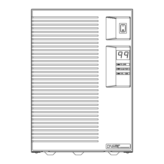
Page 30: Front Panel Features And Controls
Once the UPS is correctly installed, the front panel Features and display provides all necessary operating information. To operate an ON Series UPS: Controls 1. Plug the unit into an AC power source. 2. Plug the load equipment into the UPS. -
Page 31: Front Panel Display
NOTE:Place the enclosed peel-n-stick label (located on the warranty registration card on the last page of this manual) on or near the UPS for future reference. This label provides a quick reference for interpretation of the system status codes. ON Series User Instruction Manual... -
Page 32: Back Panel Dip Switch Settings
Reserved Switches 1 and 2: Units are shipped with the interface preset to “Advanced” and “9600” to support ONEAC’s most popular UPS monitoring software accessory kits. Follow the special instructions in the accessory kit, or refer to Appendix A for information on supporting third party interface software. -
Page 33: Features And Specifications
Features and Specifications Features and Family Overview: Specifications Standard and Extended Runtime Models Standard Wall Mount Rackmount Standard Rackmount Extended Extended Extended Runtime Runtime Runtime ON400 ON600 ON900 ON1300 ON2000 ON2200 ON Series User Instruction Manual... -
Page 34: Features
Features The ON Series product family was designed for various power environments. Each part number includes a letter. This letter identifies the power environment. Please specify the part number and letter when ordering • 120 or 208/240V, 60Hz applications=A. Example: ON400A-SN. -
Page 35: Options
• Digital load meter with output overload protection and recovery indication Options The ON Series units can be customized to suit your particular computing environment. Special types of receptacles, such as hospital grade and country specific, are available. -
Page 36: Physical And Electrical Specifications
Batteries: sealed, maintenance-free lead acid with a 3 – 6 year typical lifetime Recharge time to 60% available capacity: 4 hours per battery cabinet All units have temperature sensitive chargers and provide thermal isolation for battery pack. ON Series User Instruction Manual... - Page 37 Sinewave 120Vac Maximum capacity (volt-amps) 1300 1850 (watts) 1300 Batteries: Sealed, Two, Two, Four, Two, Four, 12V, maintenance-free lead acid, 12V, 12V, 12V, 17AH 3–6 yr. typical life 10AH 17AH Efficiency (%) on utility, 100% load ON Series User Instruction Manual...
- Page 38 12V, 17AH 3–6 yr. typical life 10AH 17AH Efficiency (%) on utility, 100% load * Length of chassis, allow an additional 10 in. (25.40 cm.) at rear of unit to accommodate external battery cable connection. ON Series User Instruction Manual...
- Page 39 3–6 yr. typical life 10AH 17AH 17AH Efficiency (%) on utility, 100% load * Length of chassis, allow an additional 10 in. (25.40 cm.) at rear of unit to accommodate external battery cable connection. ON Series User Instruction Manual...
- Page 40 3–6 yr. typical life 10AH 17AH 17AH Efficiency (%) on utility, 100% load * Length of chassis, allow an additional 10 in. (25.40 cm.) at rear of unit to accommodate external battery cable connection. ON Series User Instruction Manual...
- Page 41 Efficiency (%) on utility, 100% load * Length of chassis, allow an additional 10 in. (25.40 cm.) at rear of unit to accommodate external battery cable connection. See page 17 for details on input and output voltages under various conditions. ON Series User Instruction Manual...
- Page 42 3–6 yr. typical 12V, life 17AH Efficiency (%) on utility, 100% load * Length of chassis, allow an additional 10 in. (25.40 cm.) at rear of unit to accommodate external battery cable connection. ON Series User Instruction Manual...
- Page 43 40 (18) Nominal input voltage 120Vac 60Hz On battery output voltage Sinewave 120Vac Maximum capacity (volt-amps): (watts): Two, Batteries: Sealed, maintenance-free lead acid, 3–6 yr. typical life 12V, 17AH Efficiency (%) on utility, 100% load ON Series User Instruction Manual...
- Page 44 40 (18) Nominal input voltage 230Vac 50/60Hz On battery output voltage Sinewave 230Vac Maximum capacity (volt-amps): (watts): Two, Batteries: Sealed, maintenance-free lead acid, 3–6 yr. typical life 12V, 17AH Efficiency (%) on utility, 100% load ON Series User Instruction Manual...
-
Page 45: Runtime Estimates
0:24 0:09 0:13 0:12 0:14 0:23 0:21 0:08 0:11 0:10 0:12 0:20 0:18 0:07 0:10 0:09 0:11 0:17 0:15 NOTE:Runtimes in the above chart are based on tests using 0.65 PF switched mode power supply. ON Series User Instruction Manual... - Page 46 6:27 9:07 70 1:34 3:33 5:33 7:51 9:53 80 1:21 3:08 4:54 6:53 8:39 90 1:11 2:48 4:23 6:10 7:43 9:24 100 1:04 2:34 3:60 5:36 6:58 8:28 NOTE:Runtimes shown are based on calculated values. ON Series User Instruction Manual...
- Page 47 6:39 8:05 80 0:53 2:12 3:25 4:47 5:53 7:06 8:32 90 0:47 2:01 3:07 4:20 5:17 6:20 7:39 9:07 100 0:42 1:51 2:51 3:59 4:47 5:43 6:55 8:16 NOTE:Runtimes shown are based on calculated values. ON Series User Instruction Manual...
- Page 48 5:33 80 0:22 1:02 1:34 2:19 2:37 2:66 3:40 4:34 90 0:18 0:49 1:16 1:56 2:09 2:28 3:02 3:48 100 0:16 0:41 1:03 1:39 1:52 2:09 2:39 3:20 NOTE:Runtimes shown are based on calculated values. ON Series User Instruction Manual...
- Page 49 4:58 80 0:19 0:53 1:21 2:03 2:18 2:38 3:14 4:02 90 0:17 0:43 1:06 1:43 1:55 2:13 2:44 3:26 100 0:17 0:37 0:59 1:34 1:47 2:06 2:37 3:15 NOTE:Runtimes shown are based on calculated values. ON Series User Instruction Manual...
- Page 50 4:17 80 0:17 0:44 1:08 1:46 1:59 2:17 2:48 3:31 90 0:17 0:38 1:00 1:34 1:47 2:06 2:36 3:15 100 0:13 0:28 0:45 1:16 1:26 1:41 2:00 2:40 NOTE:Runtimes shown are based on calculated values. ON Series User Instruction Manual...
- Page 51 4:34 6:20 7:47 9:30 80 1:12 2:33 4:03 5:36 6:52 8:20 90 1:03 2:15 3:38 5:00 6:01 7:22 8:52 100 0:55 2:00 3:16 4:29 5:29 6:33 7:54 9:05 NOTE:Runtimes shown are based on calculated values. ON Series User Instruction Manual...
- Page 52 8:36 80 0:43 1:37 2:41 3:41 4:28 5:15 6:22 7:20 90 0:36 1:23 2:21 3:12 3:52 4:29 5:27 6:19 100 0:29 1:11 2:03 2:47 3:22 3:50 4:42 5:28 NOTE:Runtimes shown are based on calculated values. ON Series User Instruction Manual...
-
Page 53: Interface Specifications
A positive signal (3 to 24V DC) with respect to pin 7 shuts down the UPS. A signal at or below ground allows the UPS to keep running. The shell of the interface connector is connected to the UPS chassis ground. ON Series User Instruction Manual... -
Page 54: Accessories
Accessories Accessories UPS Monitoring ONEAC UPS monitoring interfaces are powerful network management tools. They enhance systems Interfaces fault tolerance by providing automatic shutdown and restart, and allow network managers to access vital power and UPS status information. Basic interfacing provides signals to shutdown Lan Manager, Lan Server, and Windows NT environments. - Page 55 The Main screen provides easy viewing and interpretation of all front panel displays, product identifiers, and line voltage statistics. A Configuration Wizard walks through the configurable options with ample context-sensitive help — also allows one button reset to factory defaults. ON Series User Instruction Manual...
- Page 56 An embedded SNMP Agent (MIB II compliant) supports Subset, Basic, and Advanced compliance groups defined in the May 1994 Internet Proposed Standard UPS MIB. The ethernet card has an RJ-45 connector for 10BaseT ethernet networks. ON Series User Instruction Manual...
-
Page 57: Installing And Removing Accessory Interface Cards
Installing and Removing Accessory Interface Cards To install an optional interface card in an ON Series UPS: 1. Shut down all UPS-powered systems. Turn the UPS OFF and unplug it. 2. Identify the interface port on the back panel of the UPS. -
Page 58: Battery Considerations
ATTENTION:The batteries in this UPS are recyclable. Dispose of the batteries properly. Battery Customer maintenance of the ON Series UPS is Maintenance limited to battery enclosure replacement. Contact ONEAC’s Technical Support Department (refer to page 1, Technical Support) with any other servicing needs. -
Page 59: Battery Replacement
Rest the wires over the top of the battery with the plug kept toward the front. Once the battery pack is in place, insert the plug and attach the wire retainer and front cover. ON Series User Instruction Manual... - Page 60 Insert the new battery pack into the UPS with the molded cover toward the front. Once the battery pack is in place, insert the plug and attach the wire retainer and front cover. ON Series User Instruction Manual...
- Page 61 Rest the wires at the front and to the left of the battery. Once the battery pack is in place, insert the plug and refit the inside cover with the screw. Attach the front cover. ON Series User Instruction Manual...
-
Page 62: Units
The batteries inside the Extended Runtime enclosures are not user-replaceable. The entire battery enclosure must be replaced or the enclosure may be returned to ONEAC for battery replacement. For details, refer to Connecting Multiple Battery Enclosures on page 19. ATTENTION:Place the Main Power Unit on the top or to the side of the stackable configuration. -
Page 63: Battery Disposal
ONEAC Technical Support at +44 (0) 1235 534721. Mark the RMA number on the packing slip and shipping carton. 2. Phone ONEAC Corporation for the number of a local battery collection site (US only). 3. Make arrangements with a local auto shop that collects automotive batteries for reprocessing. -
Page 64: Troubleshooting
UPS. If there is no display, ensure that the circuit breaker located on the rear panel is pushed in. Refer to page 10, Input Protector, for more information on resetting and troubleshooting the circuit breaker. ON Series User Instruction Manual... -
Page 65: Technical Support
Troubleshooting Technical ONEAC offers 24-hour technical support. If you Support have questions or problems regarding your ON Series UPS: 1. Refer to the troubleshooting table on page 63 and page 65 for corrective or recommended action. 2. If you are unable to troubleshoot the problem, contact ONEAC’s Technical Support... - Page 66 Unplug devices until unit is loaded to disabled. (tone sounds every 60 99 percent or less. seconds) Output will shut down due to severe Reduce load, turn the unit OFF, then overload. (continuous tone until ON to reset. output off) ON Series User Instruction Manual...
- Page 67 Technical Support Department. Plug in terminator or check RJ cables on No output (no sound). the battery cabinet(s). (See page 18.) NOTE:The tone can be controlled through the Serial Port. Select On, Off, or Mute. ON Series User Instruction Manual...
- Page 68 The UPS works, but the shutdown/ panel of the UPS. Make sure they match monitoring software is not working. the software requirements. None of the above, but things are still not Contact ONEAC’s Technical Support right. Department. ON Series User Instruction Manual...
-
Page 69: Warranty
ONEAC’s option, any defective component, circuit board, or module contained within the product only when it is returned with an ONEAC Return Material Authorization (RMA) number to ONEAC or to an ONEAC-designated repair facility. In all cases, the... -
Page 70: Appendix A: Accessories Interface Capabilities
Installing ONEAC Software Use rear panel DIP switches to select the desired interface capability. ONEAC UPS control protocol (ASCII characters) communicates with ONEAC UPS monitoring software that you install on your system. Refer to Back Panel DIP Switch Settings on page 29. -
Page 71: Appendix B: Operating In Power Environments Below 110V Nominal
The inverter is disengaged when the input AC line drops 7 volts below the Max-Allow setting (default at 131V rms). ON Series User Instruction Manual... - Page 72 9600 baud, No Parity, 8 Data Bits, 1 Stop Bit. If you need to change the UPS min/max settings, use the change UPS utility pictured below. Refer to page 52 for further information on ChangeUPS. ON Series User Instruction Manual...
-
Page 73: Appendix C: Accessing Remote Off
EMO scheme. A more complete discussion of EMO issues when a UPS power source is involved is offered in ONEAC Tech Tips document “Emergency Mains Off Circuitry - July 1999.” Control of the UPS inverter is available through the standard UPS communications port (see page page 50). - Page 74 3-24V state. So, the EMO needs to reset the voltage in order for the UPS to operate as expected during a natural AC failure ON Series User Instruction Manual...
- Page 75 Appendix C: Accessing Remote Off ON Series User Instruction Manual...
Need help?
Do you have a question about the ON Series and is the answer not in the manual?
Questions and answers