Table of Contents
Advertisement
Quick Links
Remote Power Switch
International HQ
Jerusalem, Israel
Tel: + 972 2 535 9666
minicom@minicom.com
Installation Guide
w w w . m i n i c o m . c o m
North American HQ
Linden, NJ, USA
Tel: + 1 908 4862100
info.usa@minicom.com
Technical support -
European HQ
Dübendorf, Switzerland
Tel: + 41 44 823 8000
info.europe@minicom.com
support@minicom.com
5UM20160 V1.1 12/05
Advertisement
Table of Contents

Related Manuals for Minicom Remote Power Switch


Summary of Contents for Minicom Remote Power Switch
-
Page 1: Installation Guide
Remote Power Switch Installation Guide w w w . m i n i c o m . c o m International HQ North American HQ European HQ Jerusalem, Israel Linden, NJ, USA Dübendorf, Switzerland Tel: + 972 2 535 9666... -
Page 2: Table Of Contents
The RPS units................... 3 Rack mounting the RPS ................4 Installing the RPS ..................4 Installing the SNMP Utility............... 5 Safe shutdown ..................8 Operating the RPS.................. 11 Cascading RPS units................11 Technical specifications ................. 13 ©Copyright Minicom Advanced Systems... -
Page 3: Welcome
REMOTE POWER SWITCH 1. Welcome The Remote Power Switch system is produced by Minicom Advanced Systems Limited. Technical precautions This equipment generates radio frequency energy and if not installed in accordance with the manufacturer’s instructions, may cause radio frequency interference. -
Page 4: Introduction
INSTALLATION GUIDE 2. Introduction The Remote Power Switch (RPS) is an Internet ready device that remotely controls the AC power of up to 8 connected devices, such as: servers, routers, modems and telephone networks. You can cascade up to 15 Slave units to control a total of 128 devices via a 10/100 Base-T Ethernet TCP/IP connection. -
Page 5: Rack Mounting The Rps
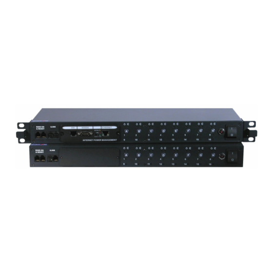
REMOTE POWER SWITCH RING ON iLINK & RESET Figure 2 RPS Slave front Circuit breaker B INPUT INPUT Power output AC input RS232 (safe shutdown) Figure 3 RPS Manager and Slave rear panel Note: The letter on the manual buttons at the front corresponds to the outlet with the same letter at the rear. -
Page 6: Installing The Snmp Utility
INSTALLATION GUIDE 2. Connect the socket of any Uninterruptible Power Supply (UPS) to the Input ports of the RPS, or connect the RPS to the power supply using the power cord. 3. Connect an Ethernet cable to Ethernet port of the RPS – see Figure 5. 4. -
Page 7: Network Selection
REMOTE POWER SWITCH Figure 6 SNMP Utility Network Selection SNMP Utility automatically searches for the computer’s network adapter. 1. From the menu click Network Selection. The Network Adapter box appears, see Figure 7. 2. Choose the network adapter that connects your computer to the LAN. -
Page 8: Advanced Tab
INSTALLATION GUIDE Figure 8 IP address for RPS Advanced tab Click the Advanced tab. Figure 9 appears. Figure 9 Advanced tab SNMP Utility provides the following security features. SNMP Utility Password By inputting a password, firmware updates to RPS by the SNMP Utility will require a password. -
Page 9: Safe Shutdown
REMOTE POWER SWITCH Management Protocol You can manage the RPS through the Web or a Telnet application. For security reasons we recommend that you change the default port numbers. Type a new port number. The full Address must then be entered to access via the Web or Telnet. - Page 10 INSTALLATION GUIDE Figure 10 Services window 4. Double-click Uninterruptible Power Supply (UPS). The UPS properties box appears. Figure 11 UPS properties box 5. From the Startup type Drop-down menu, select Automatic. 6. Click the Log On tab, Figure 12 appears. Figure 12 UPS properties box 7.
- Page 11 REMOTE POWER SWITCH 8. Click OK. 9. From the Control Panel, double-click the Power Options icon. See Figure 13. The Power Options properties box appears. Figure 13 Power Options icon 10. Select the UPS tab, the following appears. Figure 14 UPS tab 11.
-
Page 12: Operating The Rps
INSTALLATION GUIDE 13. Choose the correct COM port, and click Next. The following figure appears. Figure 16 UPS interface configuration 14. Check all 3 boxes, as shown in Figure 16, and choose Negative for the 3 voltage settings. 15. Click Finish. 9. - Page 13 REMOTE POWER SWITCH 3. Connect the iLink cable to the iLINK ports of the 2 units. See Figure 17 4. Power on the RPS Manager and the Slave. 5. Go to the RPS Setting section of the Operating Guide and change the Slave’s ID number.
-
Page 14: Technical Specifications
INSTALLATION GUIDE 11. Technical specifications Remote Power Switch Remote Power Switch Manager Slave RJ45; LAN interface 10/100M Auto-detect Modem RS232 RJ11 Reset button iLink interface 2 x RJ11, connection to cascaded unit NT safe shutdown 8 x RJ11 Power control... -
Page 15: User Guide Feedback
REMOTE POWER SWITCH User Guide Feedback Your feedback is very important to help us improve our documentation. Please email any comments to: ug.comments@minicom.com Please include the following information: Guide name, part number and version number (as appears on the front cover). - Page 16 INSTALLATION GUIDE Regional Offices Germany France Italy Kiel Vincennes Rome Tel: + 49 431 668 7933 Tel: + 33 1 49 57 00 00 Tel: + 39 06 8209 7902 info.germany@minicom.com info.france@minicom.com info.italy@minicom.com www.minicom.com...
Need help?
Do you have a question about the Remote Power Switch and is the answer not in the manual?
Questions and answers