Table of Contents
Advertisement
Advertisement
Table of Contents

Related Manuals for Binary B-300-HDMATRIX-4x4


Summary of Contents for Binary B-300-HDMATRIX-4x4
- Page 1 OWNER’S MANUAL BINARY HDMATRIX SWITCHER B-300-HDMATRIX-4x4 / B-300-HDMATRIX-8X8...
- Page 2 B-300 HDMATRIX Installation and Users Manual 4X4 & 8X8 IMPORTANT SAFETY INSTRUCTIONS WARNING: To reduce the risk of fire or electric shock, do not expose this apparatus in or near rain or moisture. 1. Read and keep these instructions for future reference. 2.
-
Page 3: Table Of Contents
1.2 Package Contents ..................................4 2 FRONT AND REAR PANEL ......................5 2.1 Front Panel B-300-HDMATRIX-4x4............................5 2.2 Front Panel B-300-HDMATRIX-8x8............................5 2.3 Rear Panel B-300-HDMATRIX-4x4 ............................6 2.4 Rear Panel B-300-HDMATRIX-8x8 ............................6 3 INSTALLATION CONSIDERATIONS ...................7 3.1 Switcher Location and Placement ............................7 3.2 Rack Installation ....................................7 4 BASIC CONNECTIONS ........................8... -
Page 4: Overview
B-300 HDMATRIX Installation and Users Manual 4X4 & 8X8 1 OVERVIEW Welcome to Binary™ - This product is engineered to provide years of exceptional reliability. Binary™ is one of the most highly regarded brands available today. We appreciate your business and we stand committed to providing our customers with the highest degree of quality and service in the industry. -
Page 5: Front And Rear Panel
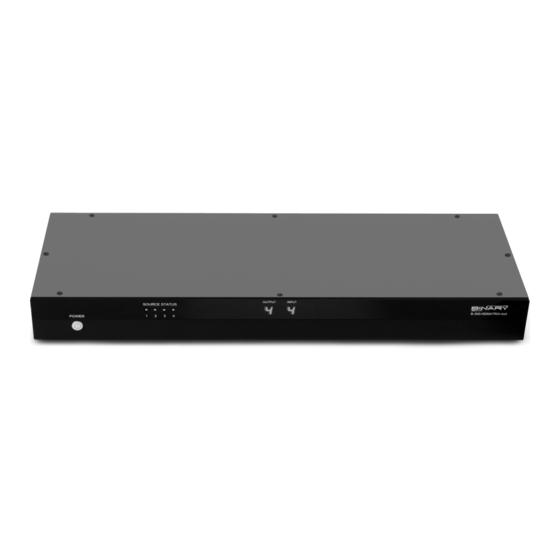
B-300 HDMATRIX Installation and Users Manual 4X4 & 8X8 2 FRONT AND REAR PANEL 2.1 FRONT PANEL B-300-HDMATRIX-4X4 1. Power: Power ON/OFF switch 2. Source Status (LED on = Source is ON and sending a signal) 3. Output: Displays the last selected Output 4. -
Page 6: Rear Panel B-300-Hdmatrix-4X4
B-300 HDMATRIX Installation and Users Manual 4X4 & 8X8 2.3 REAR PANEL B-300-HDMATRIX-4X4 1. HDMI Inputs 1 through 4 2. HDMI Outputs 1 through 4 3. RJ45 1Cat Outputs 1 through 4 (for use with B-300-HDMATRIX-RCVR only) 4. RS-232 control port (DB9) 5. -
Page 7: Installation Considerations
3 INSTALLATION CONSIDERATIONS 3.1 SWITCHER LOCATION AND PLACEMENT Binary HDMatrix switchers are designed to deliver unsurpassed technology with superior performance. How- ever, where you install the switcher can have a large effect on the performance that you receive, and the life of the unit. -
Page 8: Basic Connections
B-300 HDMATRIX Installation and Users Manual 4X4 & 8X8 4 BASIC CONNECTIONS IR Receiver Cable/Sat Blu-ray/DVD Game Player HD DVR Console HDMI HDMI HDMI HDMI Serial Cable HDMI HDMI HDMI HDMI Cat5e/Cat6 B-300-HDMATRIX- RCVR Home Automation HDMI HDTV HDTV HDTV HDTV HD Projector HDMI Sources... -
Page 9: Ir Control Connections
IR Signal (Tip) 5.2.2 Custom Cable Construction To IR Control System/ To B-300-HDMATRIX Connecting Block IR Signal (Tip) (Tip) (Ring) GND (Sleeve) 12V DC 12V DC (Sleeve) (Sleeve) GND (Ring) IR Signal (Tip) IR Signal (Tip) pg.9 © 2012 Binary... -
Page 10: Ir Control And Bi-Directional Ir
4. All IR Out All IR signals coming from a room via the B-300-HDMATRIX-4x4 (IR Output From Room) are summed on this output. Connect an IR Flasher, IR Connecting Block or Automation System to this connection. If control of the B-300 HDMATRIX-4x4 from rooms is required, use an IR Flasher connected to the From Room output or the All IR Output, and place near the IR Receiver on the front panel of the B-300-HDMATRIX-4x4. -
Page 11: Rs232 Serial Control
B-300 HDMATRIX Installation and Users Manual 4X4 & 8X8 7 RS232 SERIAL CONTROL The Binary™ HDMatrix receives control data on pin 2 (Rxd – Data Receive) and transmits control data on pin 3 (TxD - Data Transmit). The connection cable between the HD MATRIX and the Automation System will need to be configured so that pin2 (RxD) on the HD MATRIX is connected to the Automation Systems Txd pin, and pin3 (TxD) on the HD MATRIX is connected to the Automation Systems Rxd (Receive Data) pin. -
Page 12: Edid Configuration
The stored EDID is per source, so all display locations will see the same resolution and have the same audio format when that source is selected. The B-300-HDMATRIX-4x4 and B-300-HDMATRIX-8x8 provide sophisticated EDID management designed to make sure that each source provides audio and video output that is compatible with all displays using that source. -
Page 13: Advanced Edid Configuration
If you have such a display, you will need to use a Learned EDID from the display to store in the Input EDID of any sources that will be routed to that display. pg.13 © 2012 Binary... -
Page 14: Setting Edid For Single Input
B-300 HDMATRIX Installation and Users Manual 4X4 & 8X8 8.2.1.1 Setting EDID for Single Input Example: Input =1 Embedded EDID=4 Display Readout (Example) 1. Press DEFAULT 2. Press Number Key (1-8) to select one Embedded EDID 3. Press INPUT 4. Press Number Key (1-8) to select the Input to which the EDID is applied 5. -
Page 15: Learning Edid
Note that learning the EDID for a display to all sources is the same as using Auto EDID. Example: Input=All EDID Learned from Output 4 Display Readout (Example) 1. Press LEARN 2. Press OUTPUT 3. Press Number Key (1-8) to select the Output the EDID is learned from 4. Press ENTER (success) (fail) pg.15 © 2012 Binary... -
Page 16: Edid Status
B-300 HDMATRIX Installation and Users Manual 4X4 & 8X8 8.3 EDID STATUS Once EDIDs are configured, the assigned EDID for sources can be reviewed to ensure that the desired output is configured or for troubleshooting. Example: Input=3 Display Readout (Example) EDID 5 Assigned EDID Learned from Embedded... -
Page 17: Operation And Control
5. Press ENTER Input to All Outputs Display Readout (Example) Example: Output=All Input=4 1. Press OUTPUT 2. Press ALL to select all Outputs 3. Press INPUT 4. Press Number Key (1-8) to select Input 6. Press ENTER pg.17 © 2012 Binary... -
Page 18: Turn Off (Mute) Outputs
B-300 HDMATRIX Installation and Users Manual 4X4 & 8X8 10.1.2 Turn Off (Mute) Outputs Mute one Output Example: Output=1 Display Readout (Example) 1. Press OUTPUT 2. Press Number Key (1-8) to select Output 3. Press OUTPUT OFF 4. Press ENTER Mute All Outputs Display Readout (Example) 1. -
Page 19: Specifications
(L x W x H) Package 21” x 10.4” x 3.1” 21”x10.4”x3.1” Weight 5.4 lbs 5.8 lbs Mounting 1RU rack‐mount. Ears included 1RU rack‐mount. Ears included Power supply 12 5A DC 12V 5A DC Power consumption 60 Watts [max] 60 Watts [max] Operation temperature 32~104°F] 32~104°F] Storage temperature ‐20~60°C ‐4~140°F ‐20~60°C ‐4~140°F Relative humidity 20~90% RH [no condensation] 20~90% RH [no condensation] pg.19 © 2012 Binary... -
Page 20: Warranty
12 WARRANTY Two-Year Limited Warranty ™ This Binary product has a 2-year limited Warranty. This warranty includes parts and labor repairs on all components found to be defective in material or workmanship under normal conditions of use. This warranty shall not apply to products which have been abused, modified or disassembled. - Page 21 © 2012 Binary 120601-930...
Need help?
Do you have a question about the B-300-HDMATRIX-4x4 and is the answer not in the manual?
Questions and answers