Table of Contents
Advertisement
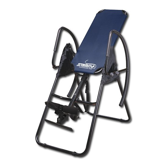
Product May Vary Slightly From Pictured.
WARNING: The Buckle Strap and the Nylon Strap must be
attached and properly adjusted at all times during
use of this product.
CAUTION: Weight on this product should not exceed 250 lbs.
This Product is Distributed Exclusively by
2040 N. Alliance, Springfield, MO 65803
www.staminaproducts.com
Customer Service
1 (800) 375-7520
Owner's
Manual
Exercise can present a
h e a l t h r i s k . C o n s u l t a
physician before beginning
any exercise program with
this equipment. If you feel
faint or dizzy, immediately
d i s c o n t i n u e u s e o f t h i s
equipment. Serious bodily
i n j u r y c a n o c c u r i f t h i s
equipment is not assembled
and used correctly. Serious
bodily injury can also occur
if all instructions are not
followed. Keep others and
pets away from equipment
when in use. Always make
sure all bolts and nuts are
securely tightened prior to
each use. Follow all safety
instructions in this manual.
When calling for parts or
service, please specify
the following number :
Model#: 55-1529B
STAMINA PRODUCTS
MADE IN CHINA
©
2011 Stamina Products, Inc.
2011, 03
Advertisement
Table of Contents

Related Manuals for Stamina 55-1529B


Summary of Contents for Stamina 55-1529B
- Page 1 CAUTION: Weight on this product should not exceed 250 lbs. This Product is Distributed Exclusively by STAMINA PRODUCTS MADE IN CHINA 2040 N. Alliance, Springfield, MO 65803 Customer Service © 2011 Stamina Products, Inc. 1 (800) 375-7520 2011, 03 www.staminaproducts.com...
-
Page 2: Table Of Contents
TABLE OF CONTENTS Safety Instructions ........2 Storage ............14 Before You Begin ........4 Maintenance ..........14 Equipment Warning, Caution & Notice Labels ... 5 Warranty ............. 15 Hardware Identification Chart ....6 Product Parts Drawing ......16 Assembly Instructions ........ 7 Parts List ............ -
Page 3: Customer Service
Monday - Thursday, 7:30 A.M. - 5:00 P.M., Central Time. Friday, 8:00 A.M. - 3:00 P.M., Central Time. ONLINE TELEPHONE MAIL CUSTOMER SERVICE CUSTOMER SERVICE CUSTOMER SERVICE STAMINA PRODUCTS, INC. customerservice@staminaproducts.com Tel: 1 (800) 375-7520 Fax: (417) 889-8064 ATTN: Customer Service www.staminaproducts.com P.O. Box 1071 Springfield, MO. 65801-1071... -
Page 4: Before You Begin
BEFORE YOU BEGIN Thank you for choosing the Assisted Inversion Although Stamina constructs its products with Pro. We take great pride in producing this quality the finest materials and uses the highest standards product and hope it will provide many hours of of manufacturing and quality control, there can quality exercise to make you feel better, look sometimes be missing parts or incorrectly sized... -
Page 5: Equipment Warning, Caution & Notice Labels
EQUIPMENT WARNING, CAUTION & NOTICE LABELS This chart is provided to help identify the warning, caution, and notice labels on the Assisted Inversion Pro. Please take a moment to familiarize yourself with all of the warning, caution, and notice labels. Labels are larger than actual size WARNING LABEL(57) WARNING DECAL(61) -
Page 6: Hardware Identification Chart
HARDWARE IDENTIFICATION CHART This chart is provided to help identify the hardware used in the assembly process. Place the washers or the ends of the bolts or screws on the circles to check for the correct diameter. Use the small scale to check the length of the bolts and screws. -
Page 7: Assembly Instructions
ASSEMBLY INSTRUCTIONS Place all parts from the box in a cleared area and position them on the floor in front of you. Remove all packing materials from your area and place them back into the box. Do not dispose of the packing materials until assembly is completed. - Page 8 ASSEMBLY INSTRUCTIONS STEP 4 Attach the FOOTREST(13) to the HEIGHT ADJUSTMENT BEAM(12) with HEX BOLTS(M8x1.25x50mm) (47), WASHERS(M8)(51), and NYLOCK NUTS(M8x1.25)(49). NOTE: The five holes in the FOOTREST(13) allow the FOOTREST(13) to be attached in three different positions. Start with the center position and adjust if necessary. Use the outer position if users are taller than average.
- Page 9 ASSEMBLY INSTRUCTIONS STEP 7: Install the HEIGHT ADJUSTMENT BEAM(12) into MAIN FRAME(4) by pulling the SPRING PIN(22) on the MAIN FRAME(4) and inserting the HEIGHT ADJUSTMENT BEAM(12) as shown. For added safety, thread the SECURING KNOB(23) into the back side of the MAIN FRAME(4). WARNING: Do not use the Assisted Inversion Pro until you have verified your height setting.
- Page 10 ASSEMBLY INSTRUCTIONS STEP 10 Attach the LINKAGES(7) to the LEFT and RIGHT PIVOT ARMS(5, 6) with HEX BOLTS(M8x1.25x25mm) (46), WASHERS(M8)(51), and NYLOCK NUT(M8x1.25)(49). DO NOT OVER TIGHTEN THE BOLTS. STEP 11 Slide the LEFT and RIGHT PROTECTIVE COVERS(26, 27) onto each side of the BASE ASSEMBLY, and pull the covers down until the bottom of the covers are slightly lower than the FOLDING LINKAGES(3).
-
Page 11: Operational Instructions
OPERATIONAL INSTRUCTIONS GENERAL PRECAUTIONS Do not use the Assisted Inversion Pro alone. Always have a helper available in case assistance is needed in recovering from the decline position. Make sure that the FOAM PADS(16) and HEEL HOLDERS(19) are holding your feet securely. Make sure that the HEIGHT ADJUSTMENT BEAM(12) is properly set for your height. - Page 12 OPERATIONAL INSTRUCTIONS HEEL HOLDER USE AND ADJUSTMENT Button Place your feet on the FOOTREST(13) with your ankles between the HEEL HOLDERS(19) and FOAM PADS(16). The HEIGHT ADJUSTMENT BEAM(12) includes a lever to grip and release your feet. Pull the lever toward you until your ankles are securely held between the HEEL HOLDERS(19) and FOAM PADS(16).
- Page 13 OPERATIONAL INSTRUCTIONS USING THE INVERSION TABLE Start by lying fully back on the bed with your hands at your side, or resting on your thighs. Keeping your hands close to your body begin to raise your arms slowly allowing the table to rotate backward.
-
Page 14: Storage
STORAGE 1. To store the Assisted Inversion Pro, simply keep it in a clean dry place. MAINTENANCE The safety level of the Assisted Inversion Pro can be maintained only if it is examined regularly for damage and wear. Check the warning label, nylon strap, strap buckle, pivot arms, nylon bed, heel holders, foam pads, and spring pin for damage and wear. -
Page 15: Warranty
To implement this limited warranty, send a written notice stating your name, date, and place of purchase and a brief description of the defect along with your receipt to Stamina Products, Inc. P.O. Box 1071, Springfield Missouri, USA, 65801-1071, or email us at customerservice@staminaproducts.com, or call us at 1-800-375-7520. -
Page 16: Product Parts Drawing
PRODUCT PARTS DRAWING BACK FRONT... -
Page 17: Parts List
PARTS LIST PART# PART NAME Front Frame Rear Frame Folding Linkage Main Frame Left Pivot Arm Right Pivot Arm Linkage Left Handrail Support Right Handrail Support Handrail Locking Knob Height Adjustment Beam Footrest Inner Pad Tube Outer Pad Tube Foam Pad Heel Holder Tube Heel Holder Bracket Heel Holder... - Page 18 PARTS LIST PART# PART NAME Nylock Nut (M6 x 1) Nylock Nut (M8 x 1.25) Washer (M6) Washer (M8) Large Washer (M8) Large Washer (M6) Bolt, Round Head (M6 x 1 x 10mm) Double sided Tape Support Washer Warning Label Wrench Combination Wrench Manual...
-
Page 19: Fax/Mail Ordering Form
ATTN: Customer Service www.staminaproducts.com P.O. Box 1071 Springfield, MO. 65801-1071 Would you like to recieve email information or special offers from Stamina Products? Register at contact.staminaproducts.com TO REGISTER YOUR PRODUCT TO REGISTER YOUR PRODUCT To enact your warranty, please register your product by going to register.staminaproducts.com. Please have your product model number (printed on the cover of this owner’s manual) and the serial number (printed on the black and white sticker on your...
Need help?
Do you have a question about the 55-1529B and is the answer not in the manual?
Questions and answers