Table of Contents
Advertisement
INSTALLATION AND OPERATION INSTRUCTIONS
OWNER / INSTALLER: For your safety this manual must be carefully and thoroughly read and
understood before installing, operating or servicing this heater.
INFRARED RADIANT TUBE HEATER
Two Stage Pull Through System (Negative Pressure)
!INSTALLER: This manual is the property of the owner. Please present this manual to the
owner when you leave the job site.
▲WARNING: Improper installation, adjustment, alteration, service, or maintenance can
cause property damage, injury or death. Read the installation, operation and maintenance
instructions thoroughly before installing or servicing this equipment.
IF YOU SMELL GAS:
! ! ! ! DO NOT
DO NOT try to light any appliance.
DO NOT
DO NOT
! ! ! ! DO NOT
DO NOT touch any electrical switch; DO NOT
DO NOT
DO NOT
telephone in your building.
! ! ! ! IMMEDIATELY
IMMEDIATELY
IMMEDIATELY call your gas supplier from a neighbor's
IMMEDIATELY
telephone. Follow the gas supplier's instructions. If you
cannot reach your gas supplier, call the fire department.
!IMPORTANT: SAVE THIS MANUAL FOR FUTURE REFERENCE.
!IMPORTANT:
!IMPORTANT:
!IMPORTANT:
Post Office Box 36485 (28236) • 305 Doggett Street (28203) • Charlotte, North Carolina
Phone (704) 372-6391 • Fax (704) 332-5843 • www.spaceray.com • email: info@spaceray.com
COLD BLOCKER
CB40, CB50 – (N7/L7)
Models:
FOR YOUR SAFETY
FOR YOUR SAFETY
FOR YOUR SAFETY
FOR YOUR SAFETY
DO NOT use any
DO NOT
DO NOT
SAVE THIS MANUAL FOR FUTURE REFERENCE.
SAVE THIS MANUAL FOR FUTURE REFERENCE.
SAVE THIS MANUAL FOR FUTURE REFERENCE.
SPACE- - - - RAY
SPACE
RAY
SPACE
SPACE
RAY
RAY
DO NOT store or use gasoline or other
DO NOT
DO NOT
DO NOT
store or use gasoline or other
store or use gasoline or other
store or use gasoline or other
flammable vapors and liquids in the vicinity of
flammable vapors and liquids in the vicinity of
flammable vapors and liquids in the vicinity of
flammable vapors and liquids in the vicinity of
this or any other appliance.
this or any other appliance.
this or any other appliance.
this or any other appliance.
Form 43471030
Sept 2011
Advertisement
Table of Contents

Related Manuals for Space-Ray CB40-N7


Summary of Contents for Space-Ray CB40-N7
-
Page 1: Installation And Operation Instructions
INSTALLATION AND OPERATION INSTRUCTIONS OWNER / INSTALLER: For your safety this manual must be carefully and thoroughly read and understood before installing, operating or servicing this heater. COLD BLOCKER INFRARED RADIANT TUBE HEATER Two Stage Pull Through System (Negative Pressure) CB40, CB50 –... -
Page 2: Table Of Contents
TABLE OF CONTENTS SECTION DESCRIPTION PAGE 1.0) Safety ..............................2 2.0) Installer Responsibility ........................2 3.0) General Information........................... 2 4.0) Minimum Clearances to Combustibles ................... 4 5.0) Specifications............................5 6.0) Packing List ............................5 6.1) Accessory Packages .......................... 6 7.0) Dimensions –... -
Page 3: Safety
1.0) SAFETY This heater is a self-contained infrared radiant tube heater. Safety information required during installation and operation of this heater is provided in this manual and the labels on the product. The installation, service and maintenance of this heater must be performed by a contractor qualified in the installation and service of gas fired heating equipment. - Page 4 Although these heaters may be used in many applications other than space heating (e.g., process heating), Space-Ray will not recognize the warranty for any use other than space heating. This heater is for Indoor Installation and Covered Patio Installation only and can be used in either Vented or Unvented mode.
-
Page 5: Minimum Clearances To Combustibles
4.0) MINIMUM CLEARANCES TO COMBUSTIBLES Minimum clearances to combustibles shall be measured from the outer surfaces as shown in the following diagram. For reduced clearances below the heater, use the Deflector Kit (Part No. 43504010), described in Section 6.1), and maintain the minimum clearances specified in the notes below. Follow the instructions packaged with the kit for installation. -
Page 6: Specifications
8’ * MOUNT HEATERS AS HIGH AS POSSIBLE. Minimums are shown as a guideline for human comfort and uniform energy distribution for complete building heating applications. Consult your Space-Ray representative for the particulars of your installation requirements. LOWER MOUNTING KIT... -
Page 7: Accessory Packages
6.1) ACCESSORY PACKAGES A. A. A. A. Exhaust Hood Package, Part #42924000 Exhaust Hood Package, Part #42924000 Exhaust Hood Package, Part #42924000 Exhaust Hood Package, Part #42924000 Contains: Exhaust Hood Assembly, #42925540……QTY–1 #8-18 x ½ Self-Drilling Screws, #02189030……QTY–2 B. B. B. B. Lower Mounting Kit, Part #43515000 Lower Mounting Kit, Part #43515000 Lower Mounting Kit, Part #43515000 Lower Mounting Kit, Part #43515000... -
Page 8: Dimensions - Cb Series
7.0) DIMENSIONS – CB SERIES Form 43471030 Sept 2011... -
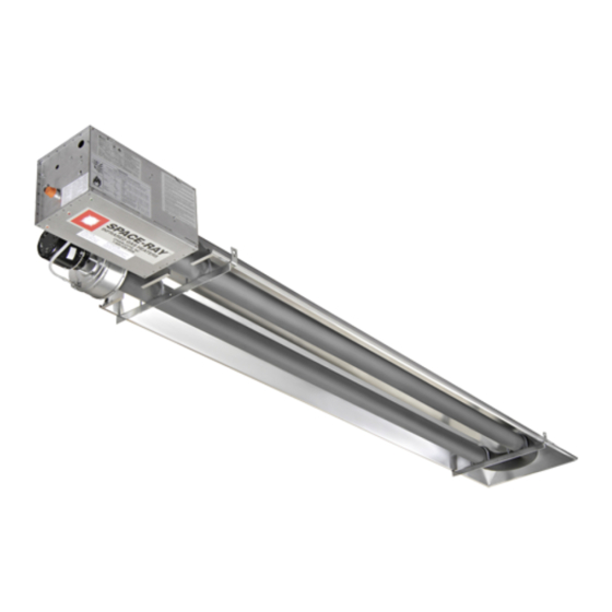
Page 9: Heater Assembly Overview
8.0) HEATER ASSEMBLY OVERVIEW Form 43471030 Sept 2011... -
Page 10: Typical Suspension Methods
6. Heaters must not be supported by gas or electric supply lines and must be suspended from a permanent structure with adequate load capacity. Space-Ray recommends that the tube sections be suspended using chains with turnbuckles. This will allow slight adjustments after assembly and heater expansion/ contraction during operation. -
Page 11: Heater Assembly
10.0) HEATER ASSEMBLY During field assembly of the heater, the recommended procedure is as follows: 1. Install suspension (according to Section 7.0) using proper suspension method (see Section 9.0). Trapeze Method Trapeze Method Trapeze Method Trapeze Method Individual Suspension Metho Individual Suspension Metho Individual Suspension Metho Individual Suspension Method d d d... - Page 12 3. Assembly the reflector onto the tube section. Leave 3” space between the tube flange and the reflector for later mounting of control box and draft inducer. 4. Place the flanges of the control end reflector flush with the end of the first reflector. Secure by sliding speed clips onto reflector edges.
- Page 13 7. Slip the plastic vacuum air tube over the 1/4” O.D. aluminum tube end of the draft inducer and the air switch probe in the control box. The air tube should be shortened to prevent a downward sag which could allow condensation build-up in the tube.
-
Page 14: Gas Connections And Regulations
ANGLE MOUNTED HEATERS O ANGLE MOUNTED HEATERS O ANGLE MOUNTED HEATERS O ANGLE MOUNTED HEATERS ONLY 10. The heater can be mounted horizontally or up to an angle of 45º maximum from horizontal. When the heater is to be angle mounted adjacent to a sidewall, make sure the draft inducer assembly is on the lower side of the heater so that the control box access panel is easily accessible. - Page 15 10. After all gas connections have been made, make sure the heater and all gas outlets are turned off before the main gas supply is turned on slowly main gas supply is turned on slowly. Turn the gas supply pressure on and check for leaks. To check for main gas supply is turned on slowly main gas supply is turned on slowly leaks, check by one of the methods listed in Appendix D of the National Fuel Gas Code.
-
Page 16: Instructions For Pressure Test Gauge Connection
12.0) INSTRUCTIONS FOR PRESSURE TEST GAUGE CONNECTION SUPPLY PRESSURE SUPPLY PRESSURE SUPPLY PRESSURE SUPPLY PRESSURE 1. The installer will provide a 1/8” N.P.T. tapped plug, accessible for test gauge connection immediately upstream of the gas supply connection to the heater. MANIFOLD PRESSURE MANIFOLD PRESSURE MANIFOLD PRESSURE... -
Page 17: Electrical Connections
13.0) ELECTRICAL CONNECTIONS ELECTRIC SHOCK HAZARD 1. All electric wiring shall conform to the latest edition of the National Electrical Code (ANSI/NFPA No. 70), or the code legally authorized in the locality where the installation is made. 2. The unit must be electrically grounded in accordance with the National Electrical Code (ANSI/NFPA No. 70-latest edition). - Page 18 SCHEMATIC SCHEMATIC SCHEMATIC SCHEMATIC WIRING DIAGRAM WIRING DIAGRAM WIRING DIAGRAM — — — — Direct Spark Ignition WIRING DIAGRAM Direct Spark Ignition Direct Spark Ignition Direct Spark Ignition Témoin vert Relais Moteur Transformateur 24ÊV pressostat Témoin rouge Bloc d'allumage électrode Témoin ambre Robinet à...
- Page 19 C. C. C. C. MANUAL SWITCH MANUAL SWITCH MANUAL SWITCH MANUAL SWITCH CONNECTIONS CONNECTIONS CONNECTIONS CONNECTIONS – – – – SINGLE HEATER SINGLE HEATER SINGLE HEATER SINGLE HEATER OPERATION OPERATION OPERATION OPERATION PER PER DUAL DUAL DUAL DUAL MANUAL SWITCH MANUAL SWITCH MANUAL SWITCH MANUAL SWITCH...
-
Page 20: Venting
14.0) VENTING CARBON MONOXIDE HAZARD A. A. A. A. BASIC FLUE VENTING BASIC FLUE VENTING BASIC FLUE VENTING BASIC FLUE VENTING — Venting must comply with the latest edition of the National Fuel Gas Code (ANSI Z223.1-latest edition) or the authority having jurisdiction. Other venting references are in the equipment volume of the ASHRAE Handbook. - Page 21 metal pipe through an exterior combustible wall, refer to latest edition of the National Fuel Gas Code or the authority having jurisdiction. 10. A venting system shall terminate at least 3 ft. above any forced air inlet located within 10 ft. VENT TERMINATION (RESIDENTIAL INSTALLATIONS) VENT TERMINATION (RESIDENTIAL INSTALLATIONS) VENT TERMINATION (RESIDENTIAL INSTALLATIONS)
- Page 22 SINGLE HEATER VENTING SINGLE HEATER VENTING SINGLE HEATER VENTING SINGLE HEATER VENTING (HORIZONTAL THROUGH SIDEWALL) (HORIZONTAL THROUGH SIDEWALL) (HORIZONTAL THROUGH SIDEWALL) (HORIZONTAL THROUGH SIDEWALL) This heater, when horizontally vented, must be installed with the approved venting system. This heater, when horizontally vented, must be installed with the approved venting system. When venting the This heater, when horizontally vented, must be installed with the approved venting system.
- Page 23 The connector length should be no more than 75% of the vertical portion of vent above the connector. • Where possible, use a Y-connector to the common vent. • 2. Material for connectors should be constructed of galvanized sheet metal or other approved noncombustible corrosion resistant material as allowed by state or local codes.
- Page 24 Multiple Heater Venting (Connections into a Manifold) VENT SIZING TABLE VENT SIZING TABLE — — — — Multiple Heater Venting VENT SIZING TABLE VENT SIZING TABLE Multiple Heater Venting Multiple Heater Venting Multiple Heater Venting Number of Heaters Number of Heaters Number of Heaters Number of Heaters 1 1 1 1...
-
Page 25: Air For Combustion
15.0) AIR FOR COMBUSTION If indoor combustion air is to be supplied for a tightly enclosed area, one square inch of free area opening shall be provided below the heater for each 1,000 Btu/hr per hour of heater input. When outside air is used, the opening below the heater shall be one square inch of free area for each 4,000 Btu/hr of heater input. - Page 26 Vertical Through the roof Horizontal Through Sidewall Form 43471030 Sept 2011 -25-...
-
Page 27: Lighting And Shutdown Instructions
16.0) LIGHTING AND SHUTDOWN INSTRUCTIONS 1. Turn on the gas and electrical supply. Rotate the gas valve knob counter-clockwise to the “ON” position. 2. Set the thermostat to call for heat. The blower motor will energize. 3. Ignition should occur after the 30-second air pre-purge. 4. -
Page 28: Control Component Location
18.0) CONTROL COMPONENT LOCATION NOTE: NOTE: NOTE: NOTE: Access panel Access panel Access panel Access panel only only only ope only opens ns ns ns to to to to 90 90° ° ° ° ..Form 43471030 Sept 2011 -27-... -
Page 29: Cleaning And Annual Maintenance
19.0) CLEANING AND ANNUAL MAINTENANCE ELECTRIC SHOCK & EXPLOSION HAZARD This heater must be cleaned and serviced annually by a qualified contractor before the start of each heating season and at any time excessive accumulation of dust and dirt is observed. Maximum heating efficiency and clean combustion will be maintained by keeping the heater clean. -
Page 30: Troubleshooting Guide
20.0) TROUBLESHOOTING GUIDE Form 43471030 Sept 2011 -29-... - Page 31 Form 43471030 -30- Sept 2011...
- Page 32 Form 43471030 Sept 2011 -31-...
- Page 33 Form 43471030 -32- Sept 2011...
-
Page 34: Replacing Parts
REPLACING PARTS ELECTRIC SHOCK & EXPLOSION HAZARD Only use genuine Space-Ray replacement parts. Parts are available from the factory for replacement by a licensed person. Refer to the Replacement Parts Guide in Section 23.0) for all replacement parts. 21.1) REMOVAL OF SPARK ELECTRODE 1. -
Page 35: Removing Main Burner And Gas Valve
21.2) REMOVING MAIN BURNER AND GAS VALVE The main burner can be inspected without removing the burner housing from the heat exchanger tube. 1. Disconnect electrical supply and gas connection at the restrainer nipple. 2. Open the access panel and disconnect the wires from gas valve. 3. -
Page 36: Ignition System Checks
21.4) IGNITION SYSTEM CHECKS TO CHECK TO CHECK TO CHECK TO CHECK IGNITION CABLE IGNITION CABLE IGNITION CABLE..IGNITION CABLE a. Make sure that the ignition cable does not touch any metal surface. b. Make sure that connections to the stud terminal and the igniter/sensor are clean and tight. Make sure that the ignition cable provides good electrical continuity. -
Page 37: Motor And Blower Wheel Check
21.5) MOTOR AND BLOWER WHEEL CHECK If draft inducer motor fails to run: a. Check power supply to junction box. b. Check for loose or broken motor lead wire. Check to see that blower wheel turns freely and is not rubbing housing. Blower wheel may have worked loose from shaft and jammed against housing. -
Page 38: Replacement Parts Guide
23.0) REPLACEMENT PARTS GUIDE DRAFT INDUCER COMPONENTS DRAFT INDUCER COMPONENTS DRAFT INDUCER COMPONENTS DRAFT INDUCER COMPONENTS Item No. Item No. Item No. Item No. Part No. Part No. Part No. Part No. Description Description Description Description Qty. Qty. Qty. Qty. 42737000 Draft Inducer Assembly 42928000... - Page 39 43471030 Installation and Operation Instructions (not shown) 43344050 Label, Gas Connector Warning 43470000 Label, Clearance to Combustibles 42848190 Label, Nameplate 42013000 Label, “Space-Ray” Logo 43470030 Label, Warning (residential) 42834000 Label, 120V Caution 42875000 Label, Warning 43470040 Label, Operating Instructions 43470050...
- Page 40 Moteur Témoin vert Témoin rouge Transformateur 24ÊV pressostat Bloc d'allumage électrode Robinet à gaz Témoin ambre Schéma de circuit de connexion Circuit d'origine Moteur d'amorce Lampes témoins Connexions client d'aspiration Armoire de commande pressostat Robinet à gaz Écartement d'électrode 4,7Êmm Plaque à...
- Page 41 BODY COMPONENTS BODY COMPONENTS BODY COMPONENTS BODY COMPONENTS Item Item Item Item Part No. Part No. Part No. Part No. Description Description Description Description 02266010 Reflector Speed Clip 42769011 Reflector Clamp with screw (4 per heater) 42770000 “U” Bolt Clamp, 3” OD Tube (6 per heater) 02127110 “U”...
Need help?
Do you have a question about the CB40-N7 and is the answer not in the manual?
Questions and answers