Market Forge Industries Premier PS-3E Owner's Manual
Premier series electric countertop convection steamer installation, operation, maintenance and parts
Hide thumbs
Also See for Premier PS-3E:
- Installation operation & maintenance (14 pages) ,
- Parts and service manual (11 pages)
Advertisement
Table of Contents
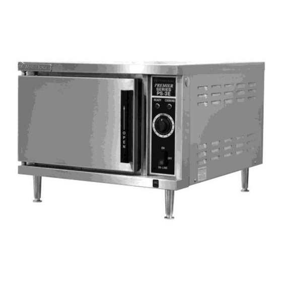
PREMIER SERIES ELECTRIC COUNTERTOP CONVECTION STEAMER
S-6011
REV.A 07/12
OWNER'S MANUAL
MODELS:
Installation, Operation, Maintenance and Parts
PS-3E (3-Pan)
PS-6E (6-Pan)
35 Garvey Street, Everett, MA 02151
Telephone (617) 387-4100, (866) 698-3188
Fax (617) 387-4456, (800) 227-2659
custserv@mfii.com
1
Advertisement
Table of Contents

Related Manuals for Market Forge Industries Premier PS-3E


Summary of Contents for Market Forge Industries Premier PS-3E
- Page 1 OWNER’S MANUAL PREMIER SERIES ELECTRIC COUNTERTOP CONVECTION STEAMER MODELS: PS-3E (3-Pan) PS-6E (6-Pan) Installation, Operation, Maintenance and Parts 35 Garvey Street, Everett, MA 02151 Telephone (617) 387-4100, (866) 698-3188 Fax (617) 387-4456, (800) 227-2659 custserv@mfii.com S-6011 REV.A 07/12...
-
Page 2: Important Notes For Installation And Operation
IMPORTANT NOTES FOR INSTALLATION AND OPERATION This is the safety alert symbol. It is used to alert you to potential personal injury hazards. Obey all safety messages that follow this symbol to avoid possible injury or death. WARNING: Improper installation, operation, adjustment, alteration, service or maintenance can cause property damage, injury or death. -
Page 3: Table Of Contents
TABLE OF CONTENTS DESCRIPTION PAGE Important Notes for Installation and Operation ................2 1.0 Service Connections ......................4 2.0 Installation Instructions ....................... 5 3.0 Operation ......................... 13 4.0 Suggested Cooking Guidelines ..................17 5.0 Cleaning ........................... 21 6.0 Maintenance ........................23 7.0 Service .......................... -
Page 4: Service Connections
1.0 SERVICE CONNECTIONS... -
Page 5: Installation Instructions
The PS-3E and PS-6E steamers are single compartment electric pressureless steam cookers with an internal electric steam generator that maintains standby water temperature at approximately 205 F. PS-3E is rated 10 kW. PS-6E is rated 15 kW. At high altitude locations a lower temperature is required to achieve atmospheric steaming. - Page 6 2.0 INSTALLATION INSTRUCTIONS (Continued) LEVELLING Using a spirit level or pan of water in the bottom of the steamer, adjust the levelling feet or the feet on the adjustable legs to level the steamer front-to-back and side-to-side. After the drain is connected, check for level by pouring water onto the floor of the compartment.
- Page 7 2.0 INSTALLATION INSTRUCTIONS (Continued) FIGURE 1 WARNING: Disconnect the power supply to the appliance before cleaning or servicing. Make electrical connection through the 1-1/8" (29 mm) diameter hole provided using 3/4" (19 mm) trade size conduit. Refer to the wiring diagram located inside the right side panel. Use 90 C minimum insulated wire.
- Page 8 2.0 INSTALLATION INSTRUCTIONS (Continued) The water supply inlets are provided with 3/8" (10 mm) compression fittings for 3/8" O.D. copper tubing. The water supply line pressure should be 25-50 PSI (1.8-3.5 kg/cm ) for each line. The water supply to the generator tank is separate from the water supply to the cooling system where steam is condensed before entering the drain line.
- Page 9 2.0 INSTALLATION INSTRUCTIONS (Continued) FIGURE 2 CAUTION: In order to avoid any backpressure in the steamer, do not connect solidly to any drain connection.
- Page 10 WATER QUALITY The water supply connected to this steamer should contain no more than 2.0 grains of hardness per gallon with pH from 6.5 to 8.0. This degree of hardness and pH can easily be obtained with the use of a properly maintained water softener. Water supplies vary from one location to another.
- Page 11 ELECTRICAL CONNECTIONS WARNING: Disconnect electrical power supply and place a tag at the disconnect switch to indicate that you are working on the circuit. Electrical grounding must be provided in accordance with local codes or in the absence of local codes, with the National Electrical Code, ANS/NFPA70, or the Canadian Electrical Code, CSA C22-2, as applicable.
- Page 12 TESTING PROCEDURES CAUTION: Live steam and accumulated hot water in the compartment may be released when the door is opened. Once the steamer is installed and all mechanical connections have been made, thoroughly test the steamer before operation. 1. Check that proper water, drain and electrical connections have been made. 2.
-
Page 13: Operation
3.0 OPERATION CAUTION: Live steam and accumulated hot water in the compartment may be released when the door is opened. CAUTION: An obstructed drain can cause personal injury or property damage. CONTROLS Main Power Switch The boiler will automatically fill and begin heating to the preset standby temperature. - Page 14 3.0 OPERATION (Continued) BEFORE FIRST USE Clean the protective oils from all surfaces of the steamer. Use a non-corrosive, grease dissolving commercial cleaner, following manufacturer’s directions. Rinse thoroughly and wipe dry with a soft clean cloth. PREHEAT Turn the main power switch ON. When the READY light comes on, set the timer to 1 minute to preheat the compartment.
- Page 15 3.0 OPERATION (Continued) CONSTANT STEAM COOKING - This mode will give continuous steam to the cooking chamber until the operator either turns the timer to the “OFF” position, or turns power OFF to the steamer. When cooking is complete, or not in use, the constant steam cooking feature should be shut off. This prevents the boiler from running unnecessarily.
- Page 16 (cans placed in 12 inch by 20 inch solid pans) or the contents may be poured into solid pans. ACCEPTABLE PAN SIZES The steamer accommodates combinations of 12" x 20" pans, solid or perforated. Number of Pans Accommodated Model Depth of Pan 1" 2.5" 4" 6" PS-3E PS-6E...
-
Page 17: Suggested Cooking Guidelines
4.0 SUGGESTED COOKING GUIDELINES COOKING HINTS Your steamer efficiently cooks vegetables or other foods for immediate serving. Steam cooking should be carefully time controlled. Keep hot food holding-time to a minimum to produce the most appetizing results. Prepare small batches, cook only enough to start serving, then cook additional amounts to meet demand. - Page 18 4.0 SUGGESTED COOKING GUIDELINES PRODUCT TIMER SETTING WEIGHT PER PAN (Minutes) Eggs 10 - 12 8 dozen Scrambled 4 dozen Hard Cooked 2 lb Rice, long grain (cover with 4 cups water/lb.) 2 lb Pasta (Place perforated pan inside solid pan, cover with cold water) Spaghetti, regular/vermicelli 12 -15...
- Page 19 PRODUCT TIMER SETTING WEIGHT PER PAN (Minutes) Lobster Tail, Frozen 10 lb Lobster, Live, 10" - 12" 4 per pan Scallops, Fresh 3 lb Scrod Fillets, Fresh 3 - 5 4 lb VEGETABLES Asparagus Spears Frozen 10 - 12 3 dozen Fresh 5 lb Beans...
- Page 20 PRODUCT TIMER SETTING WEIGHT PER PAN (Minutes) Zucchini, Slices 10 lb Canned Vegetables 10 lb can Frozen Mixed Vegetables 6 - 7 5 lb...
-
Page 21: Cleaning
5.0 CLEANING WARNING: Disconnect the power supply to the appliance before cleaning or servicing. CAUTION: Do not use cleaning agents that are corrosive. CAUTION: The appliance and its parts are hot. Use care when operating, cleaning and servicing the appliance. CAUTION: Live steam and accumulated hot water in the compartment may be released when the door is opened. - Page 22 5.0 CLEANING (Continued) Weekly, or more often if necessary: Clean exterior with a damp cloth and polish with a soft dry cloth. Use a non-abrasive cleaner to remove discolouration. CAUTION: An obstructed drain can cause personal injury or property damage. GUIDELINES FOR MAINTAINING STAINLESS STEEL SURFACES There are three things that can break down stainless steel and allow corrosion to develop: 1) Abrasion;...
-
Page 23: Maintenance
6.0 MAINTENANCE WARNING: Disconnect the power supply to the appliance before cleaning or servicing. CAUTION: Live steam and accumulated hot water in the compartment may be released when the door is opened. CAUTION: The appliance and its parts are hot. Use care when operating, cleaning and servicing the appliance. - Page 24 REMOVAL OF SCALE DEPOSITS (Continued) NOTICE: Contact the factory, the factory representative or local service company to perform maintenance and repairs. WARNING: Read and follow instructions on the CLR bottle. Use plastic or rubber gloves to avoid skin contact. If CLR comes in contact with skin, rinse with clean water.
-
Page 25: Service
7.0 SERVICE NOTICE: Contact the factory, the factory representative or local service company to perform any maintenance and repairs. ADJUSTMENT FOR HIGH ALTITUDE LOCATIONS The steamer has been factory set so that when it is ON and during the READY phase, it will maintain water temperature in the steam generator tank at approximately 205 Fahrenheit (just below water boiling point). - Page 26 7.0 SERVICE (Continued) WATER OVERFLOWS INTO COOKING COMPARTMENT When steamer is first turned on for the day, and the following conditions occur: - READY light does not come on after about 15 minutes, - Water begins to overflow into cooking compartment, - Water fill solenoid valve is open, then any or all of these symptoms may indicate a problem with the operating probe due to either:...
- Page 27 7.0 SERVICE (Continued) UNIT SHUTS DOWN WHILE IN OPERATION Pressure switch has been activated due to 5 PSI (35 kg/cm ) pressure in the generator tank. Pressure in the generator tank is caused due to plugged steam jet tubes or steam diverters due to scale or poor water conditions.
- Page 28 FIGURE 3...
-
Page 29: Parts
8.0 PARTS GENERAL ASSEMBLY FIGURE 3 ITEM MFORGE DESCRIPTION PART NO. PS-3E PS-6E 97-6254 Door Assembly 97-6373 Door Assembly 97-6295 Door Frame 97-6227 Door Frame 97-6231 Door Handle Assembly 97-6235 Decal 97-6258 Door Handle 97-6259 Door Handle Plate 98-9165 Socket Set Screw, 1/4 - 20 x 1-3/4... - Page 30 ITEM MFORGE DESCRIPTION PART NO. PS-3E PS-6E 97-6300 Steam Diverter 97-6301 Actuator Complete With Retaining Rings 97-6191 Door Switch 97-6178 Striker 97-6302 Stainless Steel Washer 97-6650 Lock Washer 97-6651 97-6270 Pilot Light, Green 97-6271 Pilot Light, Red **15 98-6046 Timer Dial...
- Page 31 ITEM MFORGE DESCRIPTION PART NO. PS-3E PS-6E 97-6285 Cooling Solenoid, 240V, Metering 97-6308 Fill Solenoid, 240V 97-6283 Blow-down Solenoid, 240V **31 97-6309 Element Assembly, 10 kW, 208V 97-6310 Element Assembly, 10 kW, 220/380V 97-6311 Element Assembly, 10 kW, 240/415V 97-6312...
- Page 32 ITEM MFORGE DESCRIPTION PART NO. PS-3E PS-6E 97-6325 Probe - 4.25" Low Level 97-6326 Probe - 3.688" High Level 97-6177 Perforated Trough 98-6089 Elbow, 1/4 c x 1/8 MPT 97-6327 Tee, 3/8 c x 1/8 MPT 98-6123 Connector, 1/4 c x 1/8 MPT...
- Page 33 ITEM MFORGE DESCRIPTION PART NO. PS-3E PS-6E 97-6342 Brass Elbow, 1/2 -14 97-6740 Brass Plug, 1/2 - 14, Hex Head 97-6344 Connector, 3/8 c x 1/8 MPT 97-6591 Connector, 3/8 c x 1/8 FPT 97-6346 Elbow 90 , 3/8 c x 3/8 MPT...
Need help?
Do you have a question about the Premier PS-3E and is the answer not in the manual?
Questions and answers