Table of Contents
Advertisement
Quick Links
Advertisement
Table of Contents

Related Manuals for Abus TVVR45020


Summary of Contents for Abus TVVR45020
-
Page 1: User Manual
ABUS Digital Recorder TVVR45020 User manual Version 1.0... - Page 2 A list of contents with the corresponding page number can be found in the index. Pay attention to the notes on the CD and in the accompanying documentation on “Web server con- trol” and “Clients Software”. These can be found on the Internet under www.abus-sc.com.
-
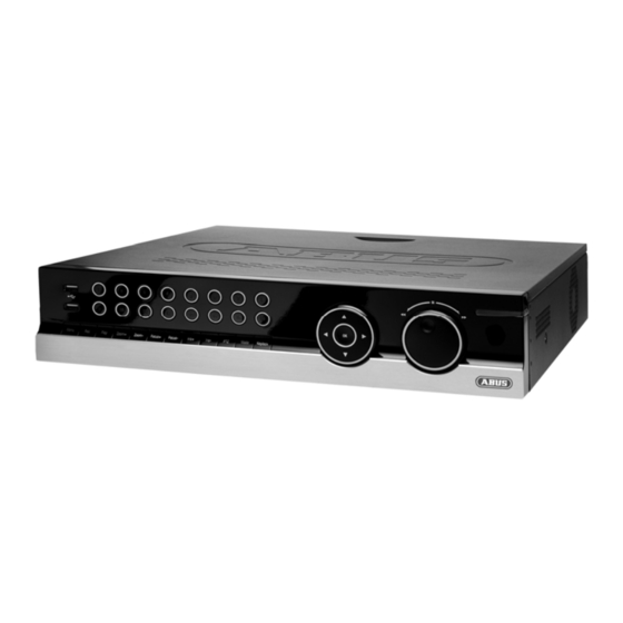
Page 3: Device Overview
Device overview Device overview See System operation on page 13. Front Rear... - Page 4 Device overview Remote control...
-
Page 5: Table Of Contents
Contents Device overview ................................3 Quick guide ..................................8 Before you start ................................8 Installing the HDD ................................8 Establishing the connections ............................8 Configuring the device ..............................8 Important safety information ............................9 ... - Page 6 Contents General settings ................................ 23 Advanced settings ..............................23 Schedule ................................... 24 Manual Record ................................24 Playback..................................25 General information ............................... 25 Playback screen ............................... 25 Using the control panel ............................. 25 Playback through video search ............................
- Page 7 Contents ShutDown ..................................45 Network ................................... 46 General information ............................... 46 Terms and definitions ............................... 46 Network layout ................................47 Network configuration ............................... 47 Alarm ....................................51 Alarm overview ................................51 Alarm Input ................................51 ...
-
Page 8: Quick Guide
Install the HDD (see the separate quick guide). Note Establish the connection to the motherboard using Check the ABUS homepage (www.abus- the red data cable (small connector). sc.com) if for this device any firmware updates Connect the power supply cable (large 5-pin connec- are available and install these tor). -
Page 9: Important Safety Information
Important safety information Important safety information Explanation of symbols General information The following symbols are used in this manual and on the Before using the device for the first time, read the follow- device: ing instructions carefully and pay attention to all warn- ings, even if you are already familiar with electronic de- Symbol Signal word Meaning vices. -
Page 10: Overloading / Overvoltage
Important safety information • To avoid the possibility of fires, the plug should al- Installation location / operating environ- ways be disconnected from the network socket if the ment device is not used for long periods. Disconnect the • Position the device on a firm, level surface and do not device from the mains power supply before impend- place any heavy objects on the device. -
Page 11: Care And Maintenance
Important safety information Care and maintenance Putting into operation Maintenance is necessary if the device has been dam- • Observe all safety and operating instructions before aged. This includes damage to the plug, mains cable and putting the device into operation for the first time. housing, penetration of the interior by liquids or foreign •... -
Page 12: Introduction
User manual graphical errors, and reserves the right to make changes to the product and operating instructions at any time and without prior warning. ABUS Se- curity-Center GmbH is not liable or responsible for direct or indirect damages resulting from the equipment, performance and use of this product. -
Page 13: System Operation
System operation System operation Name General information Function The device can be controlled as follows: Camera selection keys (1, 2, 3...): • Using the operating elements on the front of the de- Displays the camera status: vice • White: Camera is connected •... -
Page 14: Connections On The Rear Of The Device
System operation Connections on the rear of the device Operating elements on the remote control Note Note Pay attention to the overview on page 3. Pay attention to the remote control diagram on page 4. Name Function Name VIDEO SPOT OUT: BNC video output Function •... -
Page 15: Mouse Operation
System operation Name Mouse operation Function Note PTZ: Switches on PTZ control Further descriptions in these operating instruc- Enter tions are made with the mouse. • Confirms the selection The device is suitable for use with a USB mouse. • Checks / unchecks the boxes Connect the mouse to the USB port. -
Page 16: On-Screen Keyboard
System operation On-screen keyboard Switching off, locking and rebooting the The on-screen keyboard appears after clicking on a text device entry field with the mouse: Click on “ShutDown” in the main menu. The overview appears. The keys have the same function as on a computer key- board. -
Page 17: Setup Wizard
Setup wizard Setup wizard Setting up the system Setting up the administrator The setup wizard guides you through the necessary ba- Warning sic system settings. Note down the admin password. Note The following password is preset All detailed settings can be found in the device “1 2 3 4 5”... -
Page 18: Hdd Management
Setup wizard To transfer this schedule to other cameras, first se- HDD Management lect the camera (or “All” if all cameras should have Click on “Enter”. the same settings) and confirm by pressing Copy. Exit the setting by pressing OK, then click on Next. Network Settings Click on “Enter”. -
Page 19: Adding A Network Camera
Setup wizard Adding a network camera Open the main menu, got to “Settings \ Camera Man- agement” menu, click on “Add”. The available network cameras are shown at the top of the screen. • If the camera to be added does not appear, click on Refresh. -
Page 20: Live View
Live view Live view Status symbols Overview • The following symbols are displayed depending on The live view starts automatically after the device is the operating status of the device: switched on. Symbol Meaning You can also go back to the live view by pressing the Event detected Menu key repeatedly. -
Page 21: Digital Zoom
Live view Secondary monitor Single Camera Full-screen view for selected camera Multi Camera Various camera layouts The secondary monitor is used to display a different view Next Screen Displays the next camera(s) to that on the main monitor. The Switch Monitor com- mand is used to switch from the main monitor to the sec- Stop Auto- Starts the camera sequence... -
Page 22: System Settings
Live view Setting the camera output System Settings Up to 4 cameras can be set simultaneously in the live Note view. The live view can be set as follows. Click on “Set”. Open the main menu, then click on “System Settings” and then “Display Settings”: Select the display mode. -
Page 23: Record Settings
Record Settings Record Settings More Settings Set-up Detailed settings Pre-alarm Recording period before an alarm Open the main menu, then click on “System Settings” (in seconds) and then “Record Settings”: Post-alarm Recording period after an alarm (in seconds) Expiration Period (in days) after which the re- cording is deleted automatically at 00:00. -
Page 24: Schedule
Record Settings Schedule Check or uncheck the “All Day” box. When “All Day” is selected, defined times cannot be entered. The The schedule is used to specify the recording times and setting then applies for the entire day. triggers (recording type) for the cameras. Click on the To make specific time settings, uncheck the “All Day”... -
Page 25: Playback
Playback Playback Slow-motion advance General information Next recording / day Playback can be made in three different ways: Time bar: • Through the video search in the main menu • Click on the time bar with the mouse to con- •... -
Page 26: Playback: Advanced Video Search
Playback The following settings are available: Playback from the live view screen Camera Camera to be set Click on playback whilst the live view screen is shown: Video Type Schedule, motion detection, alarm or mo- Playback is controlled on the control panel: tion detection and/or alarm, manual re- cording, all File Type... -
Page 27: Ptz Control
General information PTZ control is used to access individual PTZ IP cameras Note or ABUS video servers and control them manually. Press the right mouse button when the cursor is positioned on a live image. Using the PTZ control panel The following settings can be made. -
Page 28: Ptz Settings
Exit the settings by pressing “Apply” and “OK”. Note Compare the settings with the technical data of the connected camera. If a connected camera does not work correctly, then check the entered parameters (baud rate, data bit etc.). *Only required when using the ABUS video server... -
Page 29: Tour Settings
PTZ control Tour Settings Pattern Settings Patrols are defined tours from position to position that are Patterns are defined tours from position to position that accessed in sequence on the PTZ camera. The individual are accessed in sequence on the PTZ camera. Patterns positions are presets, which should be set as detailed are recorded live. -
Page 30: Device Menu
Device menu Device menu • Menu overview When the mouse cursor is pointed at a menu, it is marked and a short description of the menu is shown The following overview shows all menus used to set and at the bottom. control the device. -
Page 31: Manual Record
Device menu Manual Record Video Search Note Parameters for Video Search Only active cameras can be selected for manual “General” tab recording. Overview of IP cameras The recording starts immediately. Used for searching the IP cameras Select the camera by checking the corresponding Video Type Continuous box. -
Page 32: Results
Device menu Results Set the parameters that should be used for search- ing for a recording. After making a search, the results screen is displayed: When searching in the “General” tab, you can open the overview by pressing “Details”: • Highlight the searched recording. -
Page 33: Video Export
Device menu Video Export 4. Click on Export to access the export screen. Note Select the connected medium used for data storage from the drop-down menu. The export function is used to store important re- cordings on connected external media, such as: If the medium is not displayed, click on Refresh. -
Page 34: Manual Alarm
Device menu Manual Alarm HDDs Note The device manages eight 3.5" SATA hard disk drives. Each of the installed HDDs must be initialised be- fore the device can be used for recording. The de- vice only detects the HDD and its assignment af- ter initialisation has been made. -
Page 35: Initialising The Hdd
Device menu Initialising the HDD Note If the initialised HDD is not displayed, check the connections. Select the HDD by checking the corresponding box. Start the process by clicking on “Init”. Confirm the prompt by pressing OK. The status bar shows the progress of the initialisa- tion. -
Page 36: Checking The Hdd Status
Device menu Warning: If only one HDD is installed and this is set to “Read-only”, then the device cannot make re- cordings. Redundancy: At least two HDDs are installed. The redundant HDD makes an extra copy of the recordings. This is used as a data backup. •... -
Page 37: System Settings
Device menu System Settings Menu Setting Page RS232 Parameters on the serial connec- tion Display Display settings and assignment of the event output Exception Behaviour of the device in excep- tional cases (HDD full, network disconnected etc.) User Adding and changing users, as- signing authorisation rights Note Note... -
Page 38: System Settings: Camera
Device menu “DST Settings” Setting Activated when box is checked From / To Date of DST start / end Daylight Saving Time Bias: Correc- DST Bias tion of the DST to the reference time “More Set- Setting tings” tab Device Name Unique specification of the device Device Number Used for unique identification when... -
Page 39: Zones: Schedule And Notification
Device menu Select “Advanced” to specify the other camera set- tings. Select the day and enter the schedule. Note You can define up to 8 time periods (each from “Advanced” tab Setting 00:00 to 00:00). The times in the individual peri- Camera Selection of the camera ods must not overlap. -
Page 40: System Settings: Record
Device menu System Settings: Record Note See description on page 23. System Settings: Network Note See separate section on page 46. System Settings: Alarm Note See separate section on page 51. System Settings: PTZ Note See description on page 27. System Settings: RS232 No function. -
Page 41: System Settings: Exception
Device menu System Settings: Exception To add a new user, select Add. Note Parameter Setting Enter the trigger under “Exception Type”, for ex- User Name Unique identification ample: Password Access code for the device (device man- • HDD Full agement) •... - Page 42 Device menu Setting the access rights Control the access rights of the user by clicking on “Permission”: Note The user can make the settings locally (i.e. on the device) or change the parameters. The user can access the device via the network connection.
-
Page 43: Maintenance
Device menu Upgrading the device Maintenance Note A device upgrade can be made from a USB de- Note vice or over the network via FTP. This menu is used for device maintenance, and • should only be operated by experienced users. Copy the upgrade file to the main directory of a USB stick. -
Page 44: Log Search
Device menu Log Search Type Minor type / sub-parameter Operation • • Switch On • ShutDown • Irregular ShutDown • Local Reboot • Local Login / Local Logout • Local Settings • • Local Recording Begin / • Local PTZ Control •... -
Page 45: Default Settings
Device menu Information Default Settings Note Note The technical data of the device is displayed in the In this process, the device is reset to the factory de- information menu. fault settings. This can be useful for support queries, for exam- ple. -
Page 46: Network
Network Network General information Parameter Setting Correct network settings are essential in the following Name The name server is responsible for as- cases: server signing a unique IP address to a web ad- • When using network cameras (IP cameras) dress or URL (e.g. -
Page 47: Network Layout
Network Network layout Parameter Setting The device must be physically connected to the network NIC Type Set the transmission speed of the in- over a CAT5 cable (see connections on page 3). stalled network card here. Tip: 10M/100M/1000M Auto Note DHCP Check the box if the IP addresses are Pay attention to the specific information and in-... - Page 48 OTHERS Email Used to specify the e-mail settings To use the ABUS DDNS function, you must first set which are sent as an e-mail to a spe- up an account under www.eytronserver.com. Please cific address in the event of an alarm.
- Page 49 Network Setting the HOST / OTHERS Setting up an e-mail address In the event of an alarm, the device can send a message Legen Sie i by e-mail. Enter the e-mail configuration here: Legen Sie i Parameter Setting Alarm Host IP No function Parameter Setting...
- Page 50 Network Enter the parameters of the e-mail notification. Click on Test to send a test e-mail. Note The device sends an e-mail to the specified re- cipients. If the e-mail is not received, check the settings and correct them. If necessary, check the spam filter of your e-mail client.
-
Page 51: Alarm
Alarm Alarm Alarm overview Parameter Setting The alarm settings regulate the type of camera surveil- Setting Check the box to make exception lance in a detailed fashion and control the device behav- settings and notification settings iour (for example, in the event of motion detection or PTZ Camera Assignment of the PTZ camera to video signal loss). - Page 52 PC with ABUS CMS soft- should be activated. For example, if ware. The software must be you have installed the ABUS IP alarm enabled and the recorder module, then you can use the set to surveillance mode on Secvest Key to activate guard mode the PC.
-
Page 53: Alarm Output
Alarm Output IP alarm module Click on “Alarm Output” in the “Alarm Settings” You can add up to three ABUS IP alarm modules menu. (CASA10010) here. After successfully connecting via the network, two alarm inputs and two alarm outputs are added to each of the “Alarm Input”... -
Page 54: Troubleshooting
Troubleshooting Troubleshooting Before calling the Service department, read the following information to determine the possible cause of a malfunction. Malfunction Cause Solution No power Mains cable not connected Connect the mains cable securely to the socket Power switch set to OFF Turn the power switch to ON No current in the power socket Use another device on the socket, where... -
Page 55: Index
Index Index Access rights 42 Email 49, 52 Network 46 Remote alarm 49 Address range 46 E-mail 39 Advanced Remote control 4, 14 Admin 41 Enable Password 37 configuration 47 Reset 45 Admin Password 17, Exception 41 Configuration 47 Resolution 23 Frame rate 23 Email 49 RS232 40... -
Page 56: Technical Data
Audio In: 2 x Cinch (2.0 V p-p, 1000 Ω) Audio Audio Out: 2 x Cinch (600 Ω) Control Mouse, remote control Software ABUS Central Management software OSD languages German, English, French, Dutch, Danish Power supply 100~240VAC, 6.3A, 50~60Hz Power consumption... -
Page 57: Disposal
Disposal Disposal Information on the EU directive on waste • Change low batteries in good time. electrical and electronic equipment • Always change all the batteries at the same time and use batteries of the same type. To protect the environment, do not dispose of the device with domestic waste at the end of its service life. -
Page 58: Glossary
An address in the computer network based on the Inter- Name used for the identification of websites on the Inter- net protocol. Allows different devices to identify them- net (e.g. www.abus-sc.de). selves in a network so that they are accessed specifi- cally. - Page 59 MPEG PPPoE Moving Picture Experts Group – International standard PPP over Ethernet (point-to-point protocol) for the compression of moving images. On some DVDs, Network transmission method used for establishing a the digital audio signals are compressed and recorded in connection over dial-up lines. Used in ADSL connections, this format.
-
Page 60: Internal Hdd
Internal HDD Internal HDD The internal hard disk drive (HDD) is very sensitive. Op- erate the device according to the following instructions in order to avoid drive errors. Important recordings should be backed up on external media to avoid unexpected data loss. - Page 61 ABUS Digital Recorder TVVR45020 Manufacturer: ABUS Security-Center GmbH & Co. KG Linker Kreuthweg 5 86444 Affing (Germany)
Need help?
Do you have a question about the TVVR45020 and is the answer not in the manual?
Questions and answers