Table of Contents
Advertisement
Quick Links
Advertisement
Table of Contents

Subscribe to Our Youtube Channel
Related Manuals for Abus TVVR25000


Summary of Contents for Abus TVVR25000
-
Page 1: User Manual
4/8-Channel 19“ Combo DVR TVVR25000 / TVVR25010 User manual Version 1.1... - Page 2 This should be also noted when this product is passed on to a third party. Therefore look after these operating instructions for future reference! A list of contents with the corresponding page number can be found in the index. All documents can also be found in the internet at www.abus-sc.com.
-
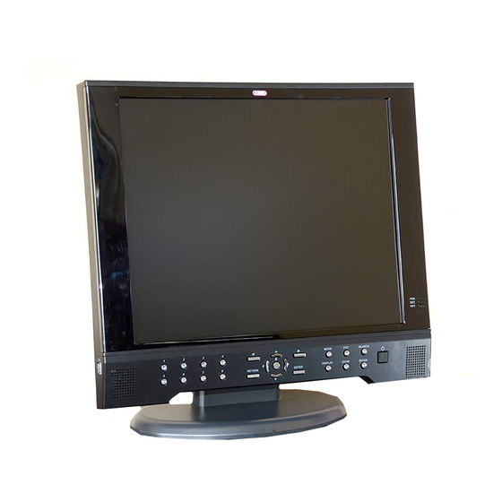
Page 3: Device Overview
Device overview Device overview See System page 12. control Front view Rear view Bottom / side view The pictures show TVVR25010 with 8 channels. DVR model TVVR25000 is similar. - Page 4 Device overview Remote control...
-
Page 5: Table Of Contents
Contents Device overview ................................3 Quick guide ..................................7 Before you start ................................7 Installing the HDD ................................7 Establishing the connections ............................7 Selecting the input ................................7 Important safety information ............................8 Explanation of symbols ..............................8 Proper use ..................................8 General information ................................. - Page 6 Contents Information on the EU directive on waste electrical and electronic equipment ............. 35 Information on handling batteries ..........................35 Important information on disposing of batteries ......................35 Information on the European RoHS directive ....................... 35 Glossary ..................................36 Overview of specialist terms ............................36 Internal HDD ...................................38...
-
Page 7: Quick Guide
Quick guide Quick guide Before you start Selecting the input The following preparatory steps must be made: You can use the 19” combo DVR as surveillance and re- cording device and at the same time as PC monitor. Pay attention to the general information, safety in- formation and notes on setting up and connecting the device (see page 8). -
Page 8: Important Safety Information
Important safety information Important safety information Explanation of symbols General information The following symbols are used in this manual and on the Before using the device for the first time, read the follow- device: ing instructions carefully and pay attention to all warn- ings, even if you are already familiar with electronic de- Symbol Signal word Meaning vices. -
Page 9: Overloading / Overvoltage
ing electrical storms, or use an uninterruptible power Installation location / operating environ- supply. ment Warning Position the device on a firm, level surface and do not place any heavy objects on the device. Never open the device on your own! There is a risk of electric shocks! The device is not designed for operation in rooms If it is necessary to open the device, consult... -
Page 10: Care And Maintenance
Care and maintenance Putting into operation Maintenance is necessary if the device has been dam- Observe all safety and operating instructions before aged. This includes damage to the plug, mains cable and putting the device into operation for the first time. housing, penetration of the interior by liquids or foreign Only open the housing to install the HDD. -
Page 11: Introduction
ABUS Se- curity-Center GmbH is not liable or responsible for direct or indirect damages resulting from the equipment, performance and use of this product. -
Page 12: System Control
System control System control General Connectors You can control the DVR by using: Note Control buttons on the front Pay attention to the overview on page 3. Remote control USB mouse Name and function Control buttons on the front panel Audio Cinch inputs Video signal BNC inputs Note... -
Page 13: Remote Control
System control ENTER Remote control Press to select an option in a menu. Note Press to display PIP when in live view mode. Pay attention to the remote control diagram on RETURN page 4. Exit a menu. Name and function Change to the DVR mode. -
Page 14: Keyboard
System control Keyboard Switching off and locking the device Click on “Power” in the main menu. The on-screen keyboard appears after clicking on a text The overview appears. entry field with the mouse: To switch off the device, select Power Off and con- firm by entering the password. -
Page 15: Live View
Live view Live view Menu bar General By clicking the icons on the menu bar you can easily ac- After the boot process the DVR automatically starts in the cess all main menus. Furthermore the current date and live view showing the LOG ON window requiring a user time, network connection, HDD usage is displayed. -
Page 16: Menu
Menu Menu CAMERA SETUP After pressing the Setup button you can choose to enter CAMERA SETUP the SYSTEM or RECORD setup. SYSTEM SETUP Camera, Display, Sound, System, User, Network, Event/Sensor, Disk Management RECORD SETUP Recording settings TITLE Camera name COVERT When it is set to ON, the camera image is SYSTEM SETUP not displayed in live display but continues... - Page 17 Menu PTZ SETUP MOTION SENSOR ADDRESS ID address of the connected PTZ cam- SENSITIVITY Between 1 (Lowest) and 10 (Highest) era. and determines the degree of motion re- PROTOCOL Protocol of the connected PTZ camera. quired before recording is activated. BAUD RATE Baud rate of the connected PTZ camera.
- Page 18 Menu DISPLAY SEQUENCE Time how long each channel is DWELL displayed in sequence operation. SPOT DWELL Time how long each screen is dis- played on the spot monitor output. DE-INTERLACE When recording any channels in MODE D1 resolution (704 x 576), this should be set to ON to prevent judder during playback.
- Page 19 Menu To add a new sequence click the ADD button and enter a SOUND Name and change the ACTIVATION. AUDIO Press ADD again in order to define a new sequence. LIVE AUDIO When it is set to ON, the selected audio channel can be monitored on the AUDIO OUTPUT.
- Page 20 Menu SYSTEM MANAGEMENT SYSTEM DATE / TIME SYSTEM S/W Version, H/W Version, Video DATE TIME Set or modify the current date and INFORMATION Signal Type, Disk Capacity, IP time. Address, MAC Address, DDNS Domain Name, Net Client Port, DATE FORMAT Determines how the date is dis- Web Server Port played.
- Page 21 Menu USER AUTHORITY USER USER MANAGEMENT Define the different rights for MANAGER and USER. SETUP Change settings. Control PTZ cameras. SEARCH Enter the SEARCH menu. ARCHIVING Enter the ARCHIVING menu. REMOTE Connect by network to the web server. AGENT Here you can manage up to 8 different users. The default 1 2 3 4 5 user is ADMIN and default password is ‚...
- Page 22 SPEED the DVR can use during a remote con- nection. DDNS To use the ABUS DDNS function, you must first set up an account at www.eytronserver.com. Please note DHCP When enabled, the DVR will obtain an the FAQs on the website when doing this.
- Page 23 Menu is used only for E-mail test (E-mail sender) TEST E-MAIL Enter an e-mail address and press TEST to send a test e-mail.
- Page 24 Menu ALARM OUTPUT EVENT/SENSOR HDD EVENT SMART Enables SMART disk monitoring. ALARM CHECK Adjust the interval the disk is checked. INTERVAL DISK FULL Determines the event ON/OFF. EVENT Determines the behavior and actions that will trigger each alarm output. ALARM INPUT ALARM OUT Choose which alarm output to config- ure.
- Page 25 Menu BUZZER OUT E-MAIL NOTIFICATION Determines the behavior and actions that will trigger the Determines the behavior and actions that will send an internal buzzer. email to a user. OPERATION The internal buzzer can be enabled or NOTIFICATIOM E-mail notification can be turned ON or disabled.
-
Page 26: Disk Manage
Menu DISK MANAGE DISK MANAGEMENT RECORD TIME In certain circumstances, it may be LIMIT necessary to limit the amount of data stored on the HDD (to comply with data protection laws for example). Recording can be limited to 12 hours, 1 day, 2 days, 3 days, 1 week or one month. -
Page 27: Record Setup
Menu RECORD SETUP SIZE/FPS/QUALITY Recording settings for each chan- nel can be defined across a 24 In this menu the recording behaviour of the DVR is set hour period, in blocks (for example between 09:00 and 18:00) or for RECORDING OPERATIONS each individual hour. - Page 28 Menu ACTIVATION PANIC RECORDING Click and hold the left mouse button to select the hours Here you can configure the recoding settings for panic and channels. After releasing the mouse button a window recording. to change the settings will open. Note During panic recording mode, the DVR will ignore all other recording settings and record continu-...
-
Page 29: Archiving
Archiving Archiving In the Archiving menu you can search for recorded data RESERVED DATA MANGEMENT and create a backup to a USB memory stick. Note To protect unauthorized viewing and distribution of data, only the ADMIN user level can archive data. NEW ARCHIVING All reserved video and snapshot files are listed here. -
Page 30: Search
Search Search In the Search menu you can search for recorded data by SEARCH BY EVENT date and time or events. Note To protect unauthorized viewing and distribution of data, only the ADMIN user level can archive data. SEARCH BY TIME Here you can search the log file for different events. -
Page 31: Web Server Access
Web server access Web server access How to establish a connection Live Mode In an internal network you can easily connect to the in- ternal web server by opening the Internet Explorer and type the IP-address and port of the DVR as below: http://IP ADDRESS:WEB SERVER PORT e.g. -
Page 32: Search Mode
Web server access Search Mode Shows the current log file. In Setup Mode you have access to all settings of the DVR and can change these remotely. Shows the control panel for connected PTZ cameras. Search Mode In the Search mode you can view recordings. You can search for recordings by using the time bar or by events. -
Page 33: Technical Data
Technical Data Technical Data Subject to alterations and errors. The dimensions are approximate values. ABUS DVR TVVR25000 TVVR25010 Video compression H.264 Camera inputs Monitor 19" Monitor Resolution 1280X1024 Camera outputs Monitor outputs 1 x BNC (1.0 V p-p, 75 ) -
Page 34: Hdd Storage Capacity
Technical Data HDD storage capacity In addition to the actual storage capacity of the installed HDD, the required storage space for recording and surveillance depends on the set resolution and frame rate of the recording. Continuous recording, 1TB HDD: Channels Resolution Quality Recording time... -
Page 35: Disposal
Disposal Disposal Information on the EU directive on waste Change low batteries in good time. electrical and electronic equipment Always change all the batteries at the same time and use batteries of the same type. To protect the environment, do not dispose of the device with domestic waste at the end of its service life. -
Page 36: Glossary
An address in the computer network based on the Inter- Name used for the identification of websites on the Inter- net protocol. Allows different devices to identify them- net (e.g. www.abus-sc.de). selves in a network so that they are accessed specifi- cally. - Page 37 MPEG PPPoE Moving Picture Experts Group – International standard PPP over Ethernet (point-to-point protocol) for the compression of moving images. On some DVDs, Network transmission method used for establishing a the digital audio signals are compressed and recorded in connection over dial-up lines. Used in ADSL connections, this format.
-
Page 38: Internal Hdd
Internal HDD Internal HDD The internal hard disk drive (HDD) is very sensitive. Op- erate the device according to the following instructions in order to avoid drive errors. Important recordings should be backed up on external media to avoid unexpected data loss. - Page 39 ABUS 19” Combo DVR TVVR25000 / TVVR25010 Manufacturer ABUS Security-Center GmbH & Co. KG Linker Kreuthweg 5 86444 Affing (Germany)
Need help?
Do you have a question about the TVVR25000 and is the answer not in the manual?
Questions and answers