Table of Contents
Advertisement
Quick Links
N
Plus
OVA
ELECTRIC, AIRLESS PAINT SPRAYER
2750 psi (195 bar) Maximum Working Pressure
Model 824–002, Series A
Complete sprayer with hose, gun,
RAC IV DripLess
Tip Guard and SwitchTip
The SHERWIN-WILLIAMS COMPANY, CLEVELAND, OHIO 44115
This manual contains important
warnings and information.
READ AND RETAIN FOR REFERENCE
COPYRIGHT 1995, GRACO INC.
OWNER'S MANUAL
824–000 Rev A
05169
Advertisement
Table of Contents

Related Manuals for Graco 824-002


Summary of Contents for Graco 824-002
- Page 1 OWNER’S MANUAL 824–000 Rev A This manual contains important warnings and information. READ AND RETAIN FOR REFERENCE Plus ELECTRIC, AIRLESS PAINT SPRAYER 2750 psi (195 bar) Maximum Working Pressure Model 824–002, Series A Complete sprayer with hose, gun, RAC IV DripLess Tip Guard and SwitchTip 05169 The SHERWIN-WILLIAMS COMPANY, CLEVELAND, OHIO 44115...
-
Page 2: Table Of Contents
Table of Contents Warnings ........Power Supply Cord . -
Page 3: Warnings
WARNING WARNING INJECTION HAZARD Spray from the gun, leaks or ruptured components can inject fluid into your body and cause ex- tremely serious injury, including the need for amputation. Fluid splashed in the eyes or on the skin can also cause serious injury. Fluid injected into the skin is a serious injury. - Page 4 WARNING WARNING EQUIPMENT MISUSE HAZARD Equipment misuse can cause the equipment to rupture or malfunction and result in serious injury. INSTRUCTIONS This equipment is for professional use only. Read all instruction manuals, tags, and labels before operating the equipment. Use the equipment only for its intended purpose. If you are not sure, call Graco Technical Assis- tance at 1–800–543–0339.
-
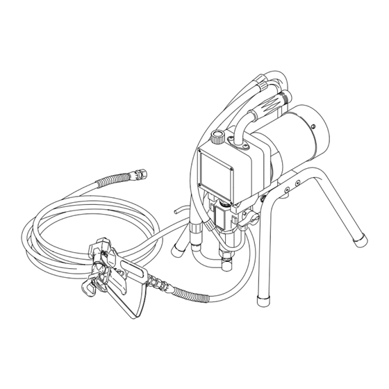
Page 5: Component Identification And Function
Component Identification and Function 02834B Fig. 1 Motor DC motor, 120 Vac, 15A, 1 phase Drive Assembly Transfers power from DC motor to the displacement pump Pressure Adjusting Knob Controls fluid outlet pressure ON/OFF Switch Power switch that controls 120 Vac power to sprayer Fluid Outlet Hose and spray gun is connected here Displacement Pump... -
Page 6: Setup
Setup 2. Fill the wet–cup (102). Pry off the wet-cup seal. WARNING Fill the cup 1/3 full with Graco Throat Seal Liquid (TSL), supplied. Install the wet-cup seal. If you supply your own hoses and spray gun, be sure the hoses are electrically conductive, that the 3. -
Page 7: Operation
Operation How to use the gun trigger safety Open or drain, position When engaged, the gun safety latch prevents the gun Closed, or spray position from accidental triggering. See Fig. 3. WARNING INJECTION HAZARD If the gun still sprays when the gun trig- ger safety is locked, repair the gun. - Page 8 Operation How to use the RAC IV tip guard. WARNING INJECTION HAZARD To reduce the risk of serious injury, Tip handle shown in whenever you are instructed to relieve spraying position. pressure, follow the Pressure Relief Turn handle 180 , Procedure on page 9.
-
Page 9: Startup
Startup NOTE: Refer to Fig. 2 and the other figures referenced WARNING in the text as you start the sprayer. INJECTION HAZARD 1. Open the pressure drain valve (42). See Fig. 7. The system pressure must be manually relieved to prevent the system from 2. - Page 10 Startup a. Increase the pressure until spray from the gun WARNING is completely atomized. To avoid excessive overspray and fogging, and to extend tip and FIRE AND EXPLOSION HAZARD sprayer life, always use the lowest pressure To reduce the risk of static sparking and needed to get the desired results.
-
Page 11: Shutdown And Care
Shutdown and Care WARNING WARNING INJECTION HAZARD INJECTION HAZARD See the warning section INJECTION To reduce the risk of serious injury, HAZARD on page 3 for information on whenever you are instructed to relieve the hazard of using damaged hoses. pressure, follow the Pressure Relief Procedure on page 9. -
Page 12: Flushing
Flushing When to Flush 3. Pour one-half gallon (2 liters) of compatible solvent into a grounded metal flushing pail. Put the suction 1. Before using a new sprayer: flush out the oil hose in the pail. which was left in to protect pump parts. 4. -
Page 13: Troubleshooting
Troubleshooting WARNING INJECTION HAZARD To reduce the risk of serious injury, whenever you are instructed to relieve pressure, follow the Pressure Relief Procedure on page 9. Basic Problem Solving Check everything in the troubleshooting table before disassembling the sprayer. TYPE OF PROBLEM WHAT TO CHECK WHAT TO DO If check is OK, go to next check... - Page 14 Basic Problem Solving TYPE OF PROBLEM WHAT TO CHECK WHAT TO DO If check is OK, go to next check When check is not OK, refer to this column Electrical 5. Check motor armature commutator for burn 5. Remove motor and have motor shop (continued) spots, gouges and extreme roughness.
- Page 15 Intermediate Problem Solving TYPE OF PROBLEM WHAT TO CHECK WHAT TO DO If check is OK, go to next check When check is not OK, refer to this column Low output 3. Release gun trigger. Observe resting position of 3. If pump consistently comes to rest with (continued) pump rod (107).
- Page 16 Intermediate Problem Solving TYPE OF PROBLEM WHAT TO CHECK WHAT TO DO When check is not OK, refer to this column If check is OK, go to next check 1. Spray tip worn beyond sprayer pressure capa- 1. Replace spray tip. Spray Pattern Variations bility.
-
Page 17: Motor Test
Motor Test WARNING INJECTION HAZARD To reduce the risk of serious injury, whenever you are instructed to relieve pressure, follow the Pressure Relief Procedure on page 9. For checking armature, motor winding and brush elec- trical continuity. Setup Remove the drive housing. See page 27. This is to ensure that any resistance you notice in the armature test is due to the motor and not to worn gears in the drive housing. -
Page 18: General Repair Information
General Repair Information WARNING WARNING INJECTION HAZARD HOT SURFACE HAZARD During operation, the motor and drive To reduce the risk of serious injury, housing become very hot and could burn whenever you are instructed to relieve your skin if touched. Flammable materi- pressure, follow the Pressure Relief als spilled on the hot, bare motor could cause a fire Procedure on page 9. -
Page 19: Motor Brushes
Motor Brushes NOTE: Replace brushes when worn to about 0.5 in. Motor lead; do not disconnect (12.5 mm). Always check both brushes. Brush Repair Minimum 0.5” (12.5 mm) Kit 821–022, which includes spring clip 821–061, is available for motors manufactured by Pacific Scientific. Included in Brush Repair Kit 821–022 NOTE: Replacement brushes may last only half as... - Page 20 Motor Brushes 9. Test the brushes. WARNING a. Remove the pump connecting rod pin (17). MOVING PARTS HAZARD See Fig. 17, page 21. Do not touch the brushes, leads, springs or brush holders while the sprayer is b. With the sprayer OFF, turn the pressure con- plugged in to reduce the risk of electric trol knob fully counterclockwise to minimum shock and serious injury.
-
Page 21: Displacement Pump Repair
Displacement Pump Repair 2. Align the hole in the rod (107) with the connecting WARNING rod assembly (15). Use a screwdriver to push the retaining spring (18) up and push in the pin (17). INJECTION HAZARD Push the retaining spring (18) into place around To reduce the risk of serious injury, the connecting rod. - Page 22 Displacement Pump Repair Intake valve repair 2. Stack these parts onto the piston valve (108) one (See Fig. 16) at a time: the backup washer (126*) and u-cup 1. Remove the suction hose. See Step 3, Removing (125*), the female gland (114*), alternately three the pump.
- Page 23 Displacement Pump Repair 3. Tighten the nut (110) onto the piston valve (108) to 6. Hand tighten the valve into the piston rod just until 2 in-lb (0.23 N.m). See Fig. 19. the nut (110) contacts the rod. See Fig. 20. 7.
- Page 24 Displacement Pump Repair 11. Place a new o-ring (116*) firmly in the cylinder 15. Torque the cylinder jam nut (117) to 73 ft-lb groove. See Fig. 21. (98 N.m). See Fig. 21. 16. Install the pump. See page 21. 12. Coat the piston rod and packings with oil. Carefully slide the assembly into the top of the cylinder (115).
-
Page 25: Motor
Motor 9. Align the new motor with the base and reinstall the WARNING screws (46). INJECTION HAZARD 10. Assemble the drive housing to the motor. Follow To reduce the risk of serious injury, steps 8 to 10 on page 27. whenever you are instructed to relieve 11. -
Page 26: Motor Start Board
5. Install the new cord (50) in the reverse order of Motor Start Board disassembly. 6. Install the junction box. Be sure no leads are WARNING pinched against the motor or by the motor start board. Also be sure the gasket (89) is installed. INJECTION HAZARD To reduce the risk of serious injury, On/Off Switch... -
Page 27: Drive Housing, Connecting Rod, Crankshaft
Drive Housing, Connecting Rod, Crankshaft WARNING CAUTION INJECTION HAZARD Do not allow the gear (16) to fall; it may stay attached to the drive housing or to the motor. To reduce the risk of serious injury, whenever you are instructed to relieve Do not lose the thrust balls (11a or 4a) or let them pressure, follow the Pressure Relief fall between the gears, which will damage the drive... - Page 28 Drive Housing, Connecting Rod, Crankshaft REF A Torque to 80 in–lb (9 N.m) Quantity of three Quantity of one Apply a total of 3 fl. oz.(29 cc) of grease to gears. 02840 Fig. 28...
-
Page 29: Pressure Control
Pressure Control 7. Loosely install the screws (63) and then torque WARNING them to 21 in–lb (2.4 N.m). INJECTION HAZARD 8. Install the front cover (13). Connect the harness (A) to the motor start board (47). To reduce the risk of serious injury, whenever you are instructed to relieve 9. -
Page 30: Pressure Transducer
Pressure Transducer WARNING INJECTION HAZARD To reduce the risk of serious injury, whenever you are instructed to relieve pressure, follow the Pressure Relief Procedure on page 9. NOTE: See Fig. 30 for this procedure. 1. Remove the displacement pump. See page 21. 2. -
Page 31: Suction Hose
Suction Hose Model 820–169 WARNING CAUTION INJECTION HAZARD Misalignment or cross-threading will damage the parts and/or create shavings which can cause the To reduce the risk of serious injury, o–ring (27) to leak. whenever you are instructed to relieve pressure, follow the Pressure Relief Procedure on page 9. -
Page 32: Drain Valve
Drain Valve Repair WARNING 1. Unscrew the spring retainer from the valve body. Remove the spring, washers and stem/ball. Clean INJECTION HAZARD any debris from the ball or seat area. To reduce the risk of serious injury, whenever you are instructed to relieve 2. -
Page 33: Displacement Pump Parts Drawing And List
Displacement Pump Parts Drawing and List Model 820–963, Series A Includes items 101 to 127 Part No. Description 820–970 MANIFOLD, pump 820–287 PACKING NUT 103* 820–286 GLAND, female, throat 103* 104* 820–285 V–PACKING, plastic, throat 105* 820–284 V–PACKING, leather, throat 106* 820–283 GLAND, male, throat... -
Page 34: Sprayer Parts Drawing
Sprayer Parts Drawing Model 824–002, Series A Label See detail on page 35 REF 33 Torque to 75–85 in-lb REF 32 OUTSIDE LABEL INSIDE LABEL... -
Page 35: Sprayer Parts List
Sprayer Parts List Model 824–002, Series A Includes items 3 to 89 as listed below Ref. Ref. Part No. Description Qty. Part No. Description Qty. 820–879 GRIP, handle 820–910 BASE, valve 821–071 MOTOR KIT 820–911 PIN, grooved, 3/32 x 1” Includes items 4a to 4f 820–912 HANDLE, drain valve... -
Page 36: Technical Data
Technical Data DANGER LABELS The English language DANGER label shown on Power Requirements ....120 VAC,60Hz, page 1 is also on your sprayer. If you have paint- 1 phase, 15 amp minimum ers who do not read English, order one of the fol- Generator... - Page 37 8X4–000 Rev. B Supersedes Rev. A Parts Change Notice Some parts in Rev. A of manual 824–000 have changed but have not yet been changed in the instruction manual. Please note the changes below and mark them in your manual or keep this sheet with your manual.
Need help?
Do you have a question about the 824-002 and is the answer not in the manual?
Questions and answers