Advertisement
Table of Contents
- 1 Table of Contents
- 2 Section 1- Introduction
- 3 Figure 1-System Diagram
- 4 Section 2- Installing the 20-1000TUL
- 5 Section 3- Installing the IFM1 Interface Module
- 6 Vanner Power Group
- 7 Section 4- Installing the Inverter Remote Status Display Panel
- 8 Figure 2- IFM1 Module Remote Wiring
- 9 Vanner Power Group
- 10 Section 5- Inverter Status Panel Operation
- 11 Section 6- Operating the 20-1000TUL Inverter
- 12 Vanner Power Group
- 13 Section 7- Troubleshooting
- 14 Section 8: GFCI Test Record
- 15 Vanner Power Group
- Download this manual
Advertisement
Table of Contents

Related Manuals for Vanner 20-1000TUL


Summary of Contents for Vanner 20-1000TUL
- Page 1 OWNER'S MANUAL Model 20-1000TUL—AC Power Inverter System OM/A96751 REV. A...
-
Page 2: Table Of Contents
Section 4— Installing the Inverter Remote Status Display Panel ......7 Section 5— Inverter Status Panel Operation ............8 Section 6— Operating the 20-1000TUL Inverter ..........9 Section 7— Troubleshooting ................10 Section 8 — GFCI Test Record ................ 11 Warranty ...................... -
Page 3: Section 1- Introduction
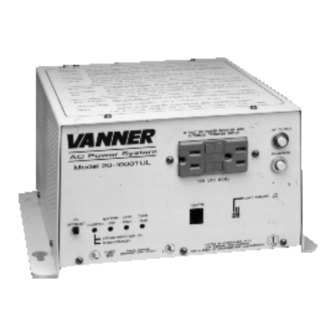
With minimum maintenance and care, you can expect years of trouble-free service from your Vanner product. The 20-1000TUL is a 12 VDC to 120 VAC inverter with a transfer relay and Ground Fault Circuit Interrupter (GFCI) protected AC output. This unit is equipped with an AC line cord for AC input power (shore/utility power) and a receptacle with a GFCI for AC output. -
Page 4: Figure 1-System Diagram
Vanner Power Group Functionality Inverter The 20-1000TUL converts battery power to 1050 Watts of 120 VAC modified sine wave power to operate vital emergency vehicle equipment. The unit is easily connected W W W W W A R N I N G... - Page 5 20-1000TUL INVERTER—OWNER'S MANUAL Vanner Power Group Specifications Inverter Inverter Inverter Inverter Inverter 20-1000TUL 20-1000TUL 20-1000TUL 20-1000TUL 20-1000TUL Output at 120 VAC RMS (Continuous Power Rating) 1050 Watts Surge Capacity at 120 VAC (3 sec) 2100 Watts Input Voltage, VDC 12 VDC, Nominal (Deep Cycle Battery Recommended) 10.5 VDC min., 16.0 VDC max.
-
Page 6: Section 2- Installing The 20-1000Tul
Step 4: Install in-line fuse. Install an in-line Bussman ANN 125 or equivalent fuse (Vanner p/n 03640- fuse and 03637-fuse holder) in the red, positive DC input cable between the battery and inverter, within 18 in. of the battery or DC wiring bus system. - Page 7 20-1000TUL INVERTER—OWNER'S MANUAL Vanner Power Group Step 7: Select Load Demand option. Select Load Demand option, if desired, using the proper switch position on the front panel Setup Switch. With Load demand ON, the inverter conserves battery energy and operates only when a load greater than 5 Watts is applied.
-
Page 8: Section 3- Installing The Ifm1 Interface Module
Manual for more information on installing the inverter and interface module in a vehicle rewired or retrofitted for the 20-1000TUL. If you are installing a new 20-1000TUL unit, you will need the interface module only if you are using the inverter status panel (p/n D06638), Remote Switch (p/n D06781), or if you require the inverter lockout feature. -
Page 9: Section 4- Installing The Inverter Remote Status Display Panel
20-1000TUL INVERTER—OWNER'S MANUAL Vanner Power Group Section 4: Installing the Inverter Remote Status Display Panel The Inverter Remote Status Display Panel (p/n D06638) contains separate, red and green LED indicators. The green indicator light signifies the inverter is On or in Standby mode. -
Page 10: Section 5- Inverter Status Panel Operation
Red Light Unit shutdown — Check the inverter's front panel LEDs for reason of shutdown: Low Battery, Overload, or Overtemp. Refer to the Troubleshooting section of this manual for fault diagnostic information. Section 6: Operating the 20-1000TUL Inverter — 8 —... -
Page 11: Vanner Power Group
Step 3: Turn on the inverter Remote Switch. Step 4: Apply shore power to the 20-1000TUL/Ambulance shore line connection. Push the ON-OFF/RESET Inverter Switch to the ON position. When powered by the AC power, the ON lamp flashes, indicating that the inverter is standing by. -
Page 12: Section 7- Troubleshooting
20-1000TUL INVERTER—OWNER'S MANUAL Vanner Power Group Section 7: Troubleshooting the 20-1000TUL The following are the most common questions heard by Vanner service professionals. If your situation does not apply to the following categories, please contact your local Vanner Power Group Service Center. -
Page 13: Section 8: Gfci Test Record
20-1000TUL INVERTER—OWNER'S MANUAL Vanner Power Group Section 8: GFCI Test Record For maximum protection against electrical shock hazard, operate the Test Switch on the Ground Fault Circuit Interrupter at least once a month. N O T E N O T E... - Page 14 6. Vanner reserves the right to repair, replace, or allow credit for any material returned under this warranty. Any damage caused by the customer will be charged or deducted from the allowance.
- Page 16 P ower Group ower Group ower Group ower Group 4282 Reynolds Drive Hilliard, Ohio 43026 Tel (614) 771-2718 Fax (614) 771-4904 Specifications Subject to Change © Copyright 1996, Vanner Weldon Inc. Printed in the U.S.A. OM/A96751 REV. A 5/96...
Need help?
Do you have a question about the 20-1000TUL and is the answer not in the manual?
Questions and answers