Advertisement
Table of Contents
- 1 Section 1: General Installation Diagram
- 2 Table of Contents
- 3 Section 2: Introduction
- 4 Section 3: Specifications
- 5 Section 4: Functionality
- 6 Section 5: Physical Dimensions
- 7 Section 6: Front and Rear Panel Component
- 8 Section 7: IMPORTANT SAFETY INSTRUCTIONS
- 9 Section 8: Installing the Lifesine LSC12-1100
- 10 Section 9: Installation and Function of the LSCR and
- 11 Section 10: Operating the Lifesine12-1100
- 12 Section 11: Fault Shutdown Conditions and Solutions
- 13 Section 12: Troubleshooting the Lifesine LSC12-1100
- Download this manual
Advertisement
Table of Contents

Related Manuals for Vanner LifeSine LSC12-1100


Summary of Contents for Vanner LifeSine LSC12-1100
- Page 1 VANNER Owner’s Manual Incorporated LifeSine True Sinewave Ambulance Inverter/Charger Model LSC12-1100 LifeSine LSC12-1100 Owner’s Manual - 1 -...
-
Page 2: Section 1: General Installation Diagram
VANNER Owner’s Manual Incorporated SECTION 1: GENERAL INSTALLATION DIAGRAM LifeSine LSC12-1100 Owner’s Manual - 2 -... -
Page 3: Table Of Contents
Section 6: Front and Rear Panel Component ................. 11 Section 7: IMPORTANT SAFETY INSTRUCTIONS ................. 16 Section 8: Installing the LifeSine LSC12-1100 ................18 Section 9: Installation and function of the LSCR and ..............22 Section 10: Operating the LifeSine12-1100 ..................24 Section 11: Fault Shutdown Conditions and Solutions ............... -
Page 4: Section 2: Introduction
Incorporated SECTION 2: INTRODUCTION Thank you for purchasing a Vanner LSC12-1100 true sine wave Ambulance Inverter/Charger for your emer- gency vehicle. We are confident you will be satisfied with its performance. Vanner products are designed and manufactured by skilled professionals using the highest standards in workmanship, guaranteeing excellent performance and reliability for your emergency vehicle. -
Page 5: Section 3: Specifications
OFF and back ON. Turn the inverter OFF and back ON, and reset the GFCI within 10 seconds before the inverter goes back into Load Demand mode. **** Allow approx. 3.5” clearance behind the inverter for access to connect/disconnect the Anderson connector. LifeSine LSC12-1100 Owner’s Manual - 5 -... -
Page 6: Section 4: Functionality
Load Demand mode since AC power is not present. To reset the GFCI, turn the inverter OFF and ON, and reset the GFCI within 10 seconds. The inverter always starts up “out of Load Demand mode” for 10 seconds. LifeSine LSC12-1100 Owner’s Manual - 6 -... - Page 7 OFF/ON for the change to go into effect. The LifeSine LSC12-1100 must be connected to the battery and battery voltage must be above 10.5V for the charger/transfer switch to turn ON. The battery charger function WILL NOT TURN ON if battery voltage is below 10.5V.
- Page 8 Battery voltage is held at Float Voltage. Charging current varies as needed to hold battery voltage constant. The charger will switch to Bulk charge stage if charging current remains at “Bulk charging amps” for more than approximately 5-30 seconds. LifeSine LSC12-1100 Owner’s Manual - 8 -...
- Page 9 The 12V DC OUTPUT Power Circuit is protected by a 20 Amp ATO fuse labeled DC Fuse, located beside the output terminal on the front of the inverter. LifeSine LSC12-1100 Owner’s Manual - 9 -...
-
Page 10: Section 5: Physical Dimensions
VANNER Owner’s Manual Incorporated SECTION 5: PHYSICAL DIMENSIONS 10.63 2x ⌀.283 4x ⌀.374 11.4 9.76 9.13 2x ⌀.642 2x ⌀.283 4.13 3.32 2.76 10.6 11.6 LifeSine LSC12-1100 Owner’s Manual - 10 -... -
Page 11: Section 6: Front And Rear Panel Component
SECTION 6: FRONT AND REAR PANEL COMPONENT Identification and Description of Operation 12 VOLT DC POWER INVERTER BATTERY CHARGER/CONDITIONER AUTOMATIC TRANSFER SWITCH Experience Power... Experience Vanner. FUSE 12VDC Factory 1 2 3 4 5 6 1 2 3 4 5 6 7 8... - Page 12 Multiple signals will not harm the LifeSine but will perform as parallel switches. When retrofitting the LifeSine into a system that has two remote control signals, see Section 8: Installation; Step 9: Remote Control, LifeSine LSC12-1100 Owner’s Manual - 12 -...
- Page 13 If a fault occurs, the unit will temporarily shut down and try to restart approximately 3 times. If the fault re- mains, the unit will latch OFF. Reset the unit by turning it OFF and back ON. LifeSine LSC12-1100 Owner’s Manual...
- Page 14 If the unit has shut down for a fault, reset the inverter by cycling the ON/OFF/REMOTE Switch OFF and back ON, or, if there is a remote switch, by cycling a remote switch OFF/ON. LifeSine LSC12-1100 Owner’s Manual - 14 -...
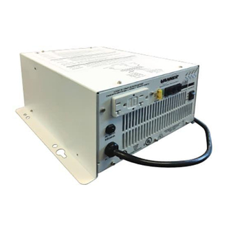
- Page 15 VANNER Owner’s Manual Incorporated Rear panel LSC12-1100 View of back panel and intake fan DC input connector (175 AMP Anderson Connecter) Chassis ground Cooling Air Intake Fan and Finger Guard LifeSine LSC12-1100 Owner’s Manual - 15 -...
-
Page 16: Section 7: Important Safety Instructions
Use of an attachment not recommended or sold by the manufacturer may result in a risk of fire, electric shock, or injury to persons. Do not disassemble unit. Return to Vanner when service or repair is required. Incorrect reassem- bly may result in a risk of electric shock or fire. - Page 17 Connect and disconnect DC output connections only after turning unit OFF and removing shore power. GROUNDING INSTRUCTIONS The chassis of this unit should be connected to vehicle chassis. Connections to unit should com- ply with all local codes and ordinances. LifeSine LSC12-1100 Owner’s Manual - 17 -...
-
Page 18: Section 8: Installing The Lifesine Lsc12-1100
VANNER Owner’s Manual Incorporated SECTION 8: INSTALLING THE LIFESINE LSC12-1100 Unpacking 1. Inspect the shipping container and equipment for loose or damaged parts. If any damage is found, imme- diately notify the freight carrier. 2. An Accessory Pack is included with the LifeSine that contains the necessary Anderson style DC cable connector and associated parts. - Page 19 The fuse should be located within 18 inches of (or as close as practical to) the battery or DC wiring bus system. Vanner recommends using; Bussmann ANN-150 Fuse (Vanner #014838) and #4164 Fuse Holder (Vanner #03637). Bussmann AMG-150 Fuse (Vanner #010098) and Vanner “ShortSafe” Fuse Holder D018361.
- Page 20 GND signal, an automotive relay will need to be added. This may be the case when the LifeSine is replacing an older inverter. See Automotive Relay sketch on the next page. LifeSine LSC12-1100 Owner’s Manual - 20 -...
- Page 21 Symptom: The LifeSine inverter does not turn OFF when the remote switch is turned OFF. Cause: Older Vanner ambulance inverter remote control arrangements (the LifeStar and the IFM1), could accept two remote control signals. The inverter treated two remote signals as if two switches were operat- ing in series.
-
Page 22: Section 9: Installation And Function Of The Lscr And
Remote Mounting Pattern Two optional remote status display panels are available for the LifeSine LSC12-1100. One is for Charger Status (Part Number – LSCR) and the other is for Inverter Status (Part Number – LSIR). (These are the same remote status display panels used with the Vanner LifeStar inverter/charger.) Both the Charger and Inverter Remote Status Display Panels contain a green and a red LED indicator light. - Page 23 Maintenance. Green Inverter switch OFF Charger in Float/ Maintenance. Blinking Green Green Inverter switch ON Low Battery Warning Low Battery Shutdown Blinking Green Blinking Green Overload Shutdown Blinking Green Blinking Green Overtemp Shutdown LifeSine LSC12-1100 Owner’s Manual - 23 -...
-
Page 24: Section 10: Operating The Lifesine12-1100
AC loads using battery power. When shore power is restored, the unit examines the AC input for several seconds and then switches the AC loads back to be powered by shore power. Step 8: Turn Remote Switches OFF. The inverter will turn OFF. LifeSine LSC12-1100 Owner’s Manual - 24 -... -
Page 25: Section 11: Fault Shutdown Conditions And Solutions
If the inverter has shut down for a fault, correct the reason for the fault and then reset the inverter by cy- cling the ON/OFF/REMOTE Switch, or a remote switch, OFF and back ON. LifeSine LSC12-1100 Owner’s Manual - 25 -... -
Page 26: Section 12: Troubleshooting The Lifesine Lsc12-1100
Incorporated SECTION 12: TROUBLESHOOTING THE LIFESINE LSC12-1100 The following are the most common questions heard by Vanner service professionals. If your situation does not apply to the following categories, please contact your local Vanner Inc Distributor or Vanner Customer Service: 1-800-227-6937, (1-800-AC-POWER) SYMPTOM ON lamp fully illuminates. - Page 27 VANNER Owner’s Manual Incorporated Notes LifeSine LSC12-1100 Owner’s Manual - 27 -...
- Page 28 VANNER Owner’s Manual Incorporated Vanner Incorporated 4282 Reynolds Drive Hilliard, Ohio 43026 Toll free 1-800-AC POWER (1-800-227-6937) Tel: 614-771-2718 Fax: 614-771-4904 www.vanner.com e-mail: pwrsales@vanner.com Owner’s Manual Part Number D919952-C January 6 , 2021 LifeSine LSC12-1100 Owner’s Manual - 28 -...
Need help?
Do you have a question about the LifeSine LSC12-1100 and is the answer not in the manual?
Questions and answers
I have a vanner 12-1100. I’m not getting any ac out. I’ve tried resetting the gfci within 10 seconds of cycling the on/ off switch. Normally when I reset a gfci, I hear a click and the button stays in. I’m not getting that. Could the gfci be bad?