Table of Contents

Related Manuals for Vanner VLT12-300


Summary of Contents for Vanner VLT12-300
- Page 1 VANNER Owner’s Manual Incorporated VLT Series 300 Watt True Sine Wave Inverter PURE SINE WAVE INVERTER REMOTE CONTROL AC OUTPUT POWER STATUS Vout Models VLT12-300 VLT24-300 300 Watt VLT Series Inverter Owner’s Manual - 1 -...
-
Page 2: Table Of Contents
VANNER Owner’s Manual Incorporated TABLE OF CONTENTS INTRODUCTION ....................... 3 IMPORTANT SAFETY INSTRUCTIONS ............3 General Safety Precautions ......................3 Precautions When Working With Batteries ................4 SPECIFICATIONS AND FEATURES ................ 5 Specifications ..........................5 Front Panel ............................ 6 ON / OFF Control Switch ....................... 6 Remote Control Terminal ....................... -
Page 3: Introduction
VANNER Owner’s Manual Incorporated 1 INTRODUCTION Thank you for purchasing a Vanner 300 Watt VLT SERIES Inverter. We are confident that you will be satisfied with the inverter’s performance and its many features. With proper installation and care, you can look forward to years of service from this high performance product. -
Page 4: Precautions When Working With Batteries
VANNER Owner’s Manual Incorporated Precautions When Working With Batteries If battery acid contacts skin or clothing, wash immediately with soap and water. If acid enters eye, immediately flood eye with running cold water for at least 20 minutes and get medical attention immediately. -
Page 5: Specifications And Features
VANNER Owner’s Manual Incorporated 3 SPECIFICATIONS AND FEATURES 3.1 Specifications Model Number SPECIFICATIONS VLT12-300 VLT24-300 AC Power Output Rated Continuous Output 300 Watts Surge Rating 400 Watts Output Waveform True Sine Wave Total Harmonic Distortion 6% THD Typical Output Voltage 110 VAC ±... -
Page 6: Front Panel
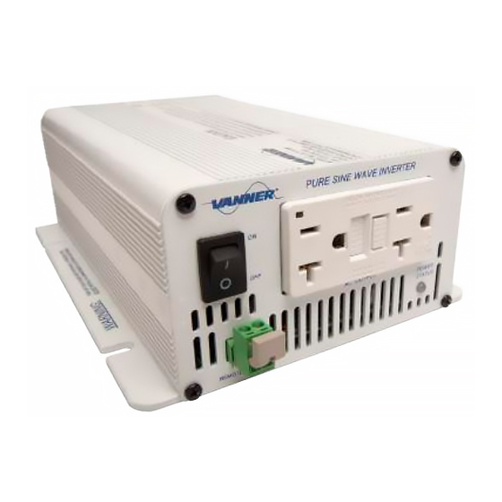
VANNER Owner’s Manual Incorporated 3.2 Front Panel PURE SINE WAVE INVERTER REMOTE CONTROL AC OUTPUT POWER STATUS Vout ON / OFF Control Switch The ON/OFF Switch must be in the ON position when using Remote Control. Remote Control Terminal A green two-terminal connector located on the front panel allows remote ON/OFF control of the inverter by a customer-supplied ON/OFF switch. -
Page 7: Power Status Led
VANNER Owner’s Manual Incorporated Power Status LED LED Display and Color Flash Pattern Status Solid Green AC Power OK Blinking Red Fast DC Over Voltage Blinking Red Slowly DC Under voltage Blinking Red Intermittently Over Temperature Solid Red AC Overload AC Output GFCI Duplex Receptacle The AC output neutral conductor is connected to AC ground and inverter chassis ground inside the inverter. -
Page 8: Rear Panel
VANNER Owner’s Manual Incorporated 3.3 Rear Panel DC INPUT WARNING: REVERSE POLARITY WILL DAMAGE UNIT. CHASSIS GROUND USE FEMALE ANDERSON PP75 CONNECTOR ONLY. DC Input Terminals DC Input terminals are Anderson Power Claw for use with Anderson PP75 Powerpole Connectors. -
Page 9: Installation
VANNER Owner’s Manual Incorporated 4 INSTALLATION 4.1 Inverter Installation Considerations Mounting: Locate a flat secure, dry, horizontal or vertical surface large enough to mount the inverter. The location should be as close to the battery as practical, usually within six feet, but not in the same compartment and should provide adequate ventilation while the inverter is operating. -
Page 10: Dc Wiring Installation Procedure
VANNER Owner’s Manual Incorporated DC Cable and Fuse Sizing Chart Model Number VLT12-300 VLT24-300 Distance from battery to inverter in feet (Total circuit length is 2 times the distance.) Wire Size 11.6 17.5 14.4 Fuse Rating 50 Amp 30 Amp... -
Page 11: Trouble Shooting
VANNER Owner’s Manual Incorporated TROUBLE SHOOTING WARNING! Do not open or disassemble the Inverter. Attempting to service the unit yourself may result in a risk of electrical shock or fire, and will void warranty. Problems and Symptoms Possible Cause Solutions No AC output voltage accompanied by the following Power Status LED flash pattern. - Page 12 VANNER Owner’s Manual Incorporated Vanner Incorporated 4282 Reynolds Drive Hilliard, Ohio 43026 Ph: 1-800-AC POWER Ph: 614-771-2718 Fax: 614-771-4904 www.vanner.com Manual P/N: D914634-B March 11, 2011 300 Watt VLT Series Inverter Owner’s Manual - 12 -...
Need help?
Do you have a question about the VLT12-300 and is the answer not in the manual?
Questions and answers