Table of Contents
Advertisement
Models:
PIER-TVFL-IPI
ST-42TVFL-IPI
•
Important operating
and maintenance
instructions included.
WARNING
If the information in these instruc-
tions is not followed exactly, a fire
or explosion may result causing property
damage, personal injury, or death.
• Do not store or use gasoline or other flam-
mable vapors and liquids in the vicinity of this
or any other appliance.
• What to do if you smell gas
- Do not try to light any appliance
- Do not touch any electrical switch. Do not
use any phone in your building.
- Immediately call your gas supplier from a
neighbor's phone. Follow the gas suppli-
er's instructions.
- If you cannot reach your gas supplier, call
the fire department.
• Installation and service must be performed by
a qualified installer, service agency, or the gas
supplier.
1. This appliance may be installed in an aftermar-
ket, permanently located, manufactured (mobile)
home, where not prohibited by local codes.
2. This appliance is only for use with the type of gas
indicated on the rating plate. This appliance is
not convertible for use with other gases, unless
a certified kit is used.
ST-42TVFL-IPI
CAUTION
DO NOT DISCARD THIS MANUAL
•
Read, understand and follow
these instructions for safe
installation and operation.
Heat & Glo • PIER-TVFL, ST-42TVFL-IPI • 455-901 Rev. F • 8/05
PIER-TVFL-IPI
•
Leave this manual with
party responsible for
use and operation.
WARNING
HOT! DO NOT TOUCH.
SEVERE BURNS MAY RESULT.
CLOTHING IGNITION MAY RESULT.
Glass and other surfaces are hot during
operation and cool down.
• Keep children away.
• CAREFULLY SUPERVISE children in same room as
appliance.
• Alert children and adults to hazards of high
temperatures.
• Do NOT operate with protective barriers open or
removed.
• Keep clothing, furniture, draperies and other
combustibles away.
This appliance has been supplied with an integral barrier
to prevent direct contact with the fixed glass panel. Do
NOT operate the appliance with the barrier removed.
Contact your dealer or Hearth & Home Technologies if the
barrier is not present or help is needed to properly install one.
In the Commonwealth of Massachusetts:
• installation must be performed by a licensed plumber
or gas fitter;
• a CO detector shall be installed in the room where the
appliance is installed.
Installation and service of this appliance should be
performed by qualified personnel. Hearth & Home
Technologies suggests NFI certified or factory-trained
professionals, or technicians supervised
by an NFI certified professional.
Owner's Manual
Installation and Operation
1
Advertisement
Table of Contents

Related Manuals for Heat & Glo PIER-TVFL-IPI


Summary of Contents for Heat & Glo PIER-TVFL-IPI
- Page 1 Owner’s Manual Installation and Operation Models: PIER-TVFL-IPI ST-42TVFL-IPI ST-42TVFL-IPI PIER-TVFL-IPI CAUTION DO NOT DISCARD THIS MANUAL • • • Important operating Read, understand and follow Leave this manual with and maintenance these instructions for safe party responsible for instructions included.
-
Page 2: Safety And Warning Information
SAFETY AND WARNING INFORMATION READ and UNDERSTAND all instructions carefully before starting the installation. FAILURE TO FOLLOW these installation instructions may result in a possible fire hazard and will void the warranty. Prior to the first firing of the fireplace, READ the Using Your Fireplace section of the Owners Guide. -
Page 3: Table Of Contents
Safety and Warning Information ....2 Service Parts List ......... 4 Section 1: Approvals and Codes ....7 Appliance Certification........... 7 Installation Codes ..........7 Table of High Altitude Installations ........7 Contents Section 2: Getting Started......8 Introducing the Heat & Glo Gas Fireplaces ... 8 Pre-installation Preparation ........ -
Page 4: Service Parts List
ST-42TVFL-IPI Service Parts (NG, LP) Exploded Parts Diagram Beginning Manufacturing Date: 7-02 Ending Manufacturing Date: _______ 5 Log Assembly ITEM DESCRIPTION SERIAL # PART NUMBER Glass Door Assembly GLA-PIER Burner NG 501-272A Burner LP 501-273A Base Refractory (Metal) 464-292 Refractory, Rear (Metal) 464-280 Log Set Assembly (sold as complete log set only) LOGS-MS... - Page 5 PIER-TVFL-IPI Service Parts (NG, LP) Exploded Parts Diagram Beginning Manufacturing Date: 8-87 Ending Manufacturing Date: _______ 5 Log Assembly ITEM DESCRIPTION SERIAL # PART NUMBER Glass Door Assembly GLA-PIER Burner NG 501-272A Burner LP 501-273A Base Refractory (Metal) 464-292 Refractory, Rear (Metal)
- Page 6 PIER-TVFL-IPI, ST-42TVFL-IPI Service Parts (NG, LP) Exploded Parts Diagram Beginning Manufacturing Date: 7-02 Ending Manufacturing Date: ______ Intermittent Pilot Ignition Valve Assembly ITEM DESCRIPTION SERIAL # PART NUMBER High Temp Limit Switch 066-531 ON/OFF Rocker Switch 060-521A 80" Wire Assembly...
-
Page 7: Section 1: Approvals And Codes
STANDARD ST-42TVFL-IPI Underwriters B- Vent ANSI Z21.50•CGA2.22 Approvals PIER-TVFL-IPI Laboratories Decorative and Codes Installation Codes The fireplace installation must conform to local codes. Before installing the fireplace, consult the local building code agency to ensure that you are in compliance with all applicable codes, including permits and inspections. -
Page 8: Section 2: Getting Started
Introducing the Heat & Glo B-type vent gas fireplaces are designed to Heat & Glo operate with all exhaust gases expelled to the outside of the building. Gas Fireplaces The information contained in this Installers Guide, unless noted otherwise, applies to all models and gas control systems. - Page 9 When planning a fireplace installation, it’s necessary to determine: • Where the unit is to be installed. • The vent system configuration to be used. • Gas supply piping. • Electrical wiring. • Framing and finishing details. • Whether optional accessories—devices such as a fan, wall switch, or remote control—are desired.
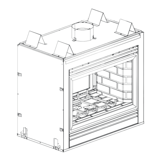
- Page 10 Figure 2. Diagram of the PIER-TVFL-IPI Heat & Glo • PIER-TVFL, ST-42TVFL-IPI • 455-901 Rev. F • 8/05...
-
Page 11: Section 3: Installing The Fireplace
Step 1 The diagram below shows space and clearance Locating the requirements for locating a fireplace within a room. Fireplace GLASS GLASS 36" 36" PIER-TVFL-IPI GLASS 36 " Installing the Fireplace VIEW 36" GLASS ST-42TVFL-IPI 1" 36" GLASS Figure 3. -
Page 12: Step 2 Framing The Fireplace
Fireplace fireplace facing material. The diagram below shows framing reference dimensions. CAUTION MEASURE FIREPLACE DIMENSIONS, AND VERIFY FRAMING METHODS AND WALL COVERING DETAILS, BEFORE FRAMING CONSTRUCTION BEGINS. PIER-TVFL-IPI ST-42TVFL-IPI FRAMING HEADERS MODEL PIER-TVFL-IPI ST-42TVFL-IPI Dimensions shown in inches. Figure 4. Framing Dimensions... -
Page 13: Step 3 Negative Pressure Make-Up Air
Negative Pressure warning: When negative pressure Step 3 is present, an atmospherically vented fireplace (with a Negative draft hood) may not function properly and it may down Pressure draft. In the case of a gas appliance, spillage of the Make-up Air combustion gases may occur. - Page 14 Detailed installation instructions for Model AK-TV Outside Air kit are found in the kit. Air Damper Before lighting the burner, open the damper plate by sliding the air damper rod, located by the gas valve, towards you. DUCT COLLAR DAMPER ASSEMBLY Figure 5.
-
Page 15: Step 4 Installing The Vent System
Step 4 A. Vent System Approvals Installing the These fireplaces are approved to use 6-inch (152mm) diameter B-type vent. B-type vent must be used Vent System when the vent system is within combustible construction. These models may also use single wall rigid or flexible gas vent IF and ONLY IF the vent system is installed within non-combustible construction such as a masonry chimney. - Page 16 4 FT. MINIMUM MAXIMUM HORIZONTAL RUN 17 FT. MAXIMUM 10 FT. MINIMUM 4 FT MINIMUM Figure 6. Vent System Attachment WARNING: THIS GAS FIREPLACE MUST NEVER BE VENTED BY CONNECTING TO A CHIMNEY FLUE SERVING A SEPARATE SOLID FUEL BURNING APPLIANCE. Heat &...
-
Page 17: Bedroom Installation In Canada
C. Bedroom Installation in Canada This model MUST NOT be vented into a vent system installed exterior to a building. The part of the vent system above the roof line can be exterior to the building. D. Vent Termination WARNING: MAJOR U.S. BUILDING CODES SPECIFY MINIMUM CHIMNEY AND/OR VENT HEIGHT ABOVE THE ROOF TOP. -
Page 18: Step 5 Positioning, Leveling, And Securing The Fireplace
Step 5 Positioning, The diagram below shows how to properly position, Leveling, and level, and secure the fireplace. Securing the Fireplace 1. Place the fireplace into position. 2. Level the fireplace from side to side and from front to back. 3. -
Page 19: Step 7 The Gas Supply Line
Step 7 NOTE: Have the gas supply line installed in The Gas accordance with local building codes by a Supply Line qualified installer approved and/or licensed as required by the locality. (In the Commonwealth of Massachusetts installation must be performed by a licensed plumber or gas fitter). NOTE: Before the first firing of the fireplace, the gas supply line should be purged of any trapped air. -
Page 20: Step 8 Gas Pressure Requirements
• At the gas line access hole, use insulation to re- pack the space around the gas pipe. • Insert insulation from the outside of the fireplace and pack the insulation tightly to totally seal between the pipe and the outer casing. The gas line should be installed by a qualified service technician. -
Page 21: Step 9 Wiring The Fireplace
Step 9 NOTE: Electrical wiring must be installed by a licensed electrician. Wiring the Fireplace Caution: Disconnect remote controls if you are absent for extended time periods. This will prevent accidental fireplace operation. Appliance Requirements • This appliance DOES NOT require 110-120 VAC to operate. - Page 22 TRANSFORMER INTERMITTENT PILOT IGNITOR 3 VAC IGNITION MODULE 3 VAC JUNCTION BOX 120 VAC JUNCTION BOX 120 VAC WALL SWITCH FAN OUTLET RECEPTACLE (NO FAN OPTION) GROUND TO FIREPLACE PLUG-IN 3V TRANSFORMER CHASSIS OPTIONAL BATTERY BACKUP OPTIONAL LOW VOLTAGE FLAME SPARKER/ REMOTE SEE NOTE 1 SENSOR...
-
Page 23: Step 10 Finishing
Step 10 The following diagram shows the minimum vertical and corresponding maximum horizontal Finishing dimensions of fireplace mantels or other combustible projections above the top front edge of the fireplace. See Figures 1, 2 and 3 for other fireplace clearances. Only non- CEILING combustible... -
Page 24: Step 11 Installing Trim, Logs & Ember Material
1/2" TOP EDGE material to the fireplace surround. SIDE EDGE 1/2" GAP BOTH ENDS PIER-TVFL-IPI 1/2" TOP EDGE SIDE EDGE 1/2" GAP Figure 12. Sealant Material Hearth Extensions A hearth extension may be desirable for aesthetic reasons. However, ANSI or CAN/CGA testing standards do not require hearth extensions for gas fireplace appliances. -
Page 25: Glass Specifications
GLASS SPECIFICATIONS: LARGE GLASS: TEMPERED SMALL GLASS: TEMPERED Heat & Glo fireplaces manufactured with tempered glass may be installed in hazardous locations such as bath- tub enclosures as defined by the CPSC. The tempered glass has been tested and certified to the requirements of ANSI Z97.1-1984 and CPSC 16 CFR 1202. -
Page 26: Step 12 Before Lighting The Fireplace
Step 12 Before lighting the fireplace, be sure to do the following: Before Lighting Remove all paperwork and documents from the Fireplace underneath the fireplace. Review safety warnings and cautions • Read the Safety and Warning Information sec- tion at the beginning of this Installers Guide. Double-check for gas leaks •... -
Page 27: Your Fireplace
Fireplace Although the frequency fireplace servicing and maintenance will depend on use and the type of Maintenance installation, you should have a qualified service technician perform an appliance check-up at the beginning of each heating season. See the table below for specific guidelines regarding each fireplace maintenance task. -
Page 28: Contact Information
Contact Information Heat & Glo, a brand of Hearth & Home Technologies Inc. 20802 Kensington Boulevard, Lakeville, MN 55044 www.fireplaces.com Please contact your Heat & Glo dealer with any questions or concerns. For the number of your nearest Heat & Glo dealer, please call 1-888-427-3973.
Need help?
Do you have a question about the PIER-TVFL-IPI and is the answer not in the manual?
Questions and answers