Table of Contents
Advertisement
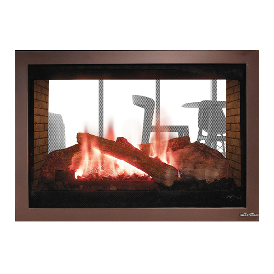
Models:
Pier-HVB-IPI
ST-HVB-IPI
•
Important operating
and maintenance
instructions included.
WARNING: If the information in these
instructions is not followed exactly, a fire
or explosion may result causing proper-
ty damage, personal injury, or death.
• Do not store or use gasoline or other flamma-
ble vapors and liquids in the vicinity of this or
any other appliance.
• What to do if you smell gas
- Do not try to light any appliance
- Do not touch any electrical switch. Do not
use any phone in your building.
- Immediately call your gas supplier from a
neighbor's phone. Follow the gas supplier's
instructions.
- If you cannot reach your gas supplier, call
the fire department.
• Installation and service must be performed by
a qualified installer, service agency, or the gas
supplier.
This appliance may be installed as an OEM installation in
manufactured home (USA only) or mobile home and must
be installed in accordance with the manufacturer's instruc-
tions and the manufactured home construction and safety
standard, Title 24 CFR, Part 3280 or Standard for Installa-
tion in Mobile Homes, CAN/CSA Z240MH.
This appliance is only for use with the type(s) of gas indi-
cated on the rating plate.
CAUTION
DO NOT DISCARD THIS MANUAL
•
Read, understand and follow
these instructions for safe
installation and operation.
Heat & Glo • PIER-HVB-IPI, ST-HVB-IPI • 2006-901 Rev. C • 12/07
Owner's Manual
Installation and Operation
•
Leave this manual with
party responsible for
use and operation.
WARNING
HOT SURFACES!
Glass and other surfaces are hot during
operation AND cool down.
Hot glass will cause burns.
•
DO NOT touch glass until it is cooled
•
NEVER allow children to touch glass
•
Keep children away
• CAREFULLY SUPERVISE children in same room as fireplace.
• Alert children and adults to hazards of high temperatures.
High temperatures may ignite clothing or other flammable
materials.
• Keep clothing, furniture, draperies and other flammable
materials away.
This appliance has been supplied with an integral barrier
to prevent direct contact with the fixed glass panel. DO
NOT operate the appliance with the barrier removed.
Contact your dealer or Hearth & Home Technologies if the
barrier is not present or help is needed to properly install one.
In the Commonwealth of Massachusetts installation must
be performed by a licensed plumber or gas fitter.
See Table of Contents for location of additional
Commonwealth of Massachusetts requirements.
Installation and service of this appliance should be
performed by qualified personnel. Hearth & Home
Technologies suggests NFI certified or factory-trained
professionals, or technicians supervised by an NFI
certified professional.
1
Advertisement
Table of Contents

Related Manuals for Heat & Glo Pier-HVB-IPI


Summary of Contents for Heat & Glo Pier-HVB-IPI
- Page 1 Mobile Homes, CAN/CSA Z240MH. This appliance is only for use with the type(s) of gas indi- cated on the rating plate. Heat & Glo • PIER-HVB-IPI, ST-HVB-IPI • 2006-901 Rev. C • 12/07 CAUTION DO NOT DISCARD THIS MANUAL •...
-
Page 2: Safety And Warning Information
Young children should be CAREFULLY SUPERVISED when they are in the same room as the appliance. Heat & Glo • PIER-HVB-IPI, ST-HVB-IPI • 2006-901 Rev. C • 12/07 These units MUST use one of the vent systems described in the Installing the Fireplace section of the Installers Guide. -
Page 3: Table Of Contents
Step 11. Before Lighting the Fireplace ... 38 Step 12. Lighting the Fireplace ... 38 After the Installation ... 38 Maintaining and Servicing Your Fireplace ... 39 Contact Information ... 40 = Contains updated information. Heat & Glo • PIER-HVB-IPI, ST-HVB-IPI • 2006-901 Rev. C • 12/07... -
Page 4: Log Assembly
Pier-HVB-IPI Service Parts Beginning Manufacturing Date: June 2003 Service Parts Diagram Ending Manufacturing Date: ______ Log Assembly Part number list on following page. Heat & Glo • PIER-HVB-IPI, ST-HVB-IPI • 2006-901 Rev. C • 12/07... - Page 5 Conversion Kit LP Pilot Orifice NG Pilot Orifice LP Regulator NG Regulator LP Additional service part numbers appear on following page. Heat & Glo • PIER-HVB-IPI, ST-HVB-IPI • 2006-901 Rev. C • 12/07 PIER-HVB-IPI SERIAL # PART NUMBER LOGS-MSB SRV2039-701...
-
Page 6: Service Parts
ST-HVB-IPI Service Parts Service Parts Diagram Beginning Manufacturing Date: June 2003 Ending Manufacturing Date: ______ Log Assembly Part number list on following page. Heat & Glo • PIER-HVB-IPI, ST-HVB-IPI • 2006-901 Rev. C • 12/07... -
Page 7: Service Part List
Conversion Kit LP Pilot Orifice NG Pilot Orifice LP Regulator NG Regulator LP Additional service part numbers appear on following page. Heat & Glo • PIER-HVB-IPI, ST-HVB-IPI • 2006-901 Rev. C • 12/07 ST-HVB-IPI SERIAL # PART NUMBER LOGS-MSB SRV2039-701... - Page 8 Battery Pack 3V Adaptor Plug NOTE: Replacement bulbs to be supplied by homeowner. Recommended replacements: Sylvania Mini Candelabra 75 watts. Heat & Glo • PIER-HVB-IPI, ST-HVB-IPI • 2006-901 Rev. C • 12/07 Service Parts Valve Assembly Parts List PIER-HVB-IPI, ST-HVB-IPI...
-
Page 9: Approvals And Codes
To identify the proper orifice size, check with the local gas utility. If installing this appliance at an elevation above 4,500 feet (in Canada), check with local authorities. Heat & Glo • PIER-HVB-IPI, ST-HVB-IPI • 2006-901 Rev. C • 12/07... -
Page 10: Requirements For The Commonwealth Of Massachusetts
(1/2) inch in size, “GAS VENT DIRECTLY BELOW. KEEP CLEAR OF ALL OB- STRUCTIONS”. Heat & Glo • PIER-HVB-IPI, ST-HVB-IPI • 2006-901 Rev. C • 12/07 Inspection The state or local gas inspector of the side wall horizontally... -
Page 11: Getting Started
Failure to follow these instructions will void the own- er’s warranty and may present a fire hazard. Heat & Glo • PIER-HVB-IPI, ST-HVB-IPI • 2006-901 Rev. C • 12/07 The Heat & Glo Warranty will be voided by, and Heat & Glo disclaims any responsibility for, the following actions: •... - Page 12 (882mm) 4-1/16 (102mm) 4-1/2 (114mm) TOP VENT COLLARS GAS CONTROLS & LABELS Figure 1. Diagram of the PIER-HVB-IPI Heat & Glo • PIER-HVB-IPI, ST-HVB-IPI • 2006-901 Rev. C • 12/07 5-1/4 (133mm) (13mm) (306mm) Ø8 (204mm) 42-5/8 Ø8 (1082mm) ACCESS...
- Page 13 (58mm) (102mm) 4-1/2 (114mm) (121mm) TOP VENT COLLARS GAS CONTROLS & LABELS Figure 2. Diagram of the ST-HVB-IPI Heat & Glo • PIER-HVB-IPI, ST-HVB-IPI • 2006-901 Rev. C • 12/07 5-14 (133mm) (306mm) Ø8 (204mm) 46-5/8 (1183mm) (1067mm) 32-5/16 (820mm)
-
Page 14: Installing The Fireplace
(25 mm). The metal ends of the fireplace may NOT be recessed into combustible construction. Heat & Glo • PIER-HVB-IPI, ST-HVB-IPI • 2006-901 Rev. C • 12/07 FINISHED WALL 45 -1/4 in. -
Page 15: Step 2. Framing The Fireplace
For minimum clearances, see the direct vent termination clearance diagrams on pages 31 and 32 in this manual. Heat & Glo • PIER-HVB-IPI, ST-HVB-IPI • 2006-901 Rev. C • 12/07 Step 2. Framing the Fireplace Fireplace framing can be built before or after the fireplace is set in place. - Page 16 (25.4mm) above the center of the horizontal vent pipe. Model PIER-HVB-IPI ST-HVB-IPI Figure 5. Framing Dimensions Heat & Glo • PIER-HVB-IPI, ST-HVB-IPI • 2006-901 Rev. C • 12/07 Framing should be constructed of 2 X 4 lumber or heavier. ST-HV-IPI 42-1/8 42-1/2...
- Page 17 1-1/4 TYP DVP48 1/2 TYP 8-9/16 12-9/16 NOTE: PIPES OVERLAP 1-1/4 INCHES AT EACH JOINT. Figure 6. DVP-Series Direct Vent Component Specifications (5-inch inner pipe / 8-inch outer pipe) Heat & Glo • PIER-HVB-IPI, ST-HVB-IPI • 2006-901 Rev. C • 12/07...
-
Page 18: Step 3. Installing The Vent System
SERIES Figure 7. Vent System Components and Termination Kits Heat & Glo • PIER-HVB-IPI, ST-HVB-IPI • 2006-901 Rev. C • 12/07 Identifying Vent Components The vent systems installed on this gas fireplace may in- clude one, two, or three 90° elbow assemblies. The rela- tionships of vertical rise to horizontal run in vent configura- tions using 90°... - Page 19 Figure 9 2. Break the Flue Restrictor into two pieces. Do this by bending the part back and forth until it breaks (see Figure 10). Heat & Glo • PIER-HVB-IPI, ST-HVB-IPI • 2006-901 Rev. C • 12/07 BREAK HERE Figure 10.
- Page 20 6’ MIN. (1.83m) 18’ MAX. (5.5m) V + H = 50’ MAX. (15.2m) Figure 14. Venting with One 90° Elbow Heat & Glo • PIER-HVB-IPI, ST-HVB-IPI • 2006-901 Rev. C • 12/07 H (FT.) H (FT.) PROPANE VENTING WITH ONE 90° ELBOW V (FT.)
- Page 21 5’ MIN. (1.5m) 10' MAX. (3.0m) 6’ MIN. (1.83m) 12' MAX. (3.6m) V + V + H = 50’ MAX. (15.2m) Figure 15. Venting with Two 90° Elbows Heat & Glo • PIER-HVB-IPI, ST-HVB-IPI • 2006-901 Rev. C • 12/07 (FT.) (FT.)
- Page 22 H + H Figure 16. Venting with Two 90° Elbows Figure 17. Venting with Two 90° Elbows Heat & Glo • PIER-HVB-IPI, ST-HVB-IPI • 2006-901 Rev. C • 12/07 VENTING WITH TWO 90° ELBOWS H + H (FT.) V (FT.) 3' MAX.
- Page 23 = 50’ MAX. (15.2m) H + H = 18’ MAX. (5.5m) Figure 18. Venting with three 90° elbows Heat & Glo • PIER-HVB-IPI, ST-HVB-IPI • 2006-901 Rev. C • 12/07 NATURAL GAS VENTING WITH THREE 90° ELBOWS (FT.) H + H (FT.)
- Page 24 5’ MIN. (1.5m) 6’ MIN. (1.83m) V+ V + H + H Figure 19. Venting with three 90° elbows Heat & Glo • PIER-HVB-IPI, ST-HVB-IPI • 2006-901 Rev. C • 12/07 NATURAL GAS H + H (FT.) 2.5’ MAX. (64mm) 3' MAX.
-
Page 25: Installing Vent Components
SHIELD ELBOW FRONT VIEW Figure 21 Heat & Glo • PIER-HVB-IPI, ST-HVB-IPI • 2006-901 Rev. C • 12/07 Venting Out Vertically elbow will be used If the vertical vent component is over 4 feet, you may want to install the flue restrictor (located in the bag containing the install manual) to improve flame appearance. - Page 26 WALL SHIELD Figure 23. 10" x 12" Hole and Vent Pipe Heat & Glo • PIER-HVB-IPI, ST-HVB-IPI • 2006-901 Rev. C • 12/07 Note: Heat shields MUST overlap by a minimum of 1-1/2 in. (38mm). The heat shield is designed to be used on a wall 4 in.
-
Page 27: Vent Termination
CEILING FIRESTOP Figure 27. Attic Firestop Heat & Glo • PIER-HVB-IPI, ST-HVB-IPI • 2006-901 Rev. C • 12/07 C. Vent Termination For Horizontal Terminations - To attach and secure the termination to the last section of horizontal vent refer to the Cinch Pipe and Termination Cap installation instructions. - Page 28 CAUTION: IF EXTERIOR WALLS ARE FINISHED WITH VINYL SIDING, IT IS SUGGESTED THAT A VINYL PROTECTOR KIT BE INSTALLED. Heat & Glo • PIER-HVB-IPI, ST-HVB-IPI • 2006-901 Rev. C • 12/07 = AIR SUPPLY INLET = AREA WHERE TERMINAL IS NOT PERMITTED = 3 ft.
- Page 29 NOTE: This also pertains to vertical vent systems in- stalled on the outside of the building. Heat & Glo • PIER-HVB-IPI, ST-HVB-IPI • 2006-901 Rev. C • 12/07 To seal the roof hole, and to divert rain and snow from the vent system: •...
-
Page 30: Step 4. Positioning, Leveling, And Securing The Fireplace
• Holes are provided in the base pan for securing the unit to the floor. Heat & Glo • PIER-HVB-IPI, ST-HVB-IPI • 2006-901 Rev. C • 12/07 Step 5. The Gas Control System WARNING: THIS UNIT IS NOT FOR USE WITH SOLID FUEL. -
Page 31: Step 6. The Gas Supply Line
• At the gas line access hole the gap between the supply piping and gas access hole can be plugged with non- combustible insulation to prevent cold air infiltration. Heat & Glo • PIER-HVB-IPI, ST-HVB-IPI • 2006-901 Rev. C • 12/07 GAS VALVE GAS LINE... -
Page 32: Step 8. Wiring The Fireplace
IPI system EXCEPT when using battery back-up. • Incorrect wiring will override IPI safety lockout and may cause explosion. Heat & Glo • PIER-HVB-IPI, ST-HVB-IPI • 2006-901 Rev. C • 12/07 BULB SOCKET IGNITION MODULE 3 VAC ASSEMBLY (3) - Page 33 This will provide the best air flow (see Figure 36). Heat & Glo • PIER-HVB-IPI, ST-HVB-IPI • 2006-901 Rev. C • 12/07 NOTE: If any of the original wire as supplied with...
-
Page 34: Wall Switch Installation For Fan (Optional)
(1/4 inch male) as shown. JUNCTION BOX Figure 37. Junction Box Wired to Wall Switch Heat & Glo • PIER-HVB-IPI, ST-HVB-IPI • 2006-901 Rev. C • 12/07 MINIMUM 14-3 AWG WITH GROUND Black... -
Page 35: Step 9. Finishing
13” 12” HOOD Minimum Vertical and Maximum Horizontal Figure 39. Dimensions of Combustibles above Fireplace Heat & Glo • PIER-HVB-IPI, ST-HVB-IPI • 2006-901 Rev. C • 12/07 12” Mantel dimensions shown are for standard hood on model: 16” 15” PIER-HVB-IPI 14”... -
Page 36: Step 10. Installing Trim, Logs & Ember Material
___________________________________________ PIER-HVB-IPI 3/8” ___________________________________________ ST-HVB-IPI 3/8” Heat & Glo • PIER-HVB-IPI, ST-HVB-IPI • 2006-901 Rev. C • 12/07 Glass Specifications Model PIER-HVB-IPI ST-HVB-IPI Heat & Glo fireplaces manufactured with tempered glass may be installed in hazardous locations such as bathtub enclosures as defined by the CPSC. -
Page 37: Placing The Ember Material
• Replace the glass door and a front trim door on the unit. Figure 42. Placement of the Ember Material Heat & Glo • PIER-HVB-IPI, ST-HVB-IPI • 2006-901 Rev. C • 12/07 Optional Ember Light Kit (Emberkit-MS) Ember Light Bulb Replacement In the lower gas valve compartment you will find three ac- cess panels for the three light bulbs (see Figure 43). -
Page 38: Step 11. Before Lighting The Fireplace
DANGEROUS and voids all war- ranties. Heat & Glo • PIER-HVB-IPI, ST-HVB-IPI • 2006-901 Rev. C • 12/07 A small amount of air will be in the gas supply lines. When first lighting the fireplace, it will take a few minutes for the lines to purge themselves of this air. -
Page 39: Maintaining And Servicing Your Fireplace
Make sure the flames are steady - not lifting or floating. See Figure 47. The flame sensor (IPI) tips should be covered with flame. See Figure 32. Heat & Glo • PIER-HVB-IPI, ST-HVB-IPI • 2006-901 Rev. C • 12/07 MAKE SURE THE FLAMES ARE STEADY—NOT LIFTING OR FLOATING. -
Page 40: Contact Information
D462436; (Canada) 1297749, 2195264, 2225408, 2313972; (Australia) 780250, 780403, 1418504 or other U.S. and foreign patents pending. Heat & Glo • PIER-HVB-IPI, ST-HVB-IPI • 2006-901 Rev. C • 12/07 Heat & Glo, a brand of Hearth & Home Technologies Inc.
Need help?
Do you have a question about the Pier-HVB-IPI and is the answer not in the manual?
Questions and answers