Escea DF700 Installation And Service Instructions Manual
Df series; dfs series
Hide thumbs
Also See for DF700:
- Installation & service instructions manual (61 pages) ,
- User manual (14 pages) ,
- Quick start manual (2 pages)

Related Manuals for Escea DF700


Summary of Contents for Escea DF700
- Page 1 Installation / Service Instructions DF / DFS -Series Gas Fireplace For the latest documentation, visit www.escea.com 630381_3...
- Page 2 AUS: Certificate of Compliance NZ: Certificates that comply with the latest legislation in accordance with national and/or local codes. If these are not issued then the Escea warranty may be void. Warranty Repair and Annual Servicing: Warranty repair work must be carried out by a recognised gas fire technician.
-
Page 4: Product Specification
DF700 PRODUCT SPECIFICATION MODEL NAME DF700 Description of Appliance Powerflued Gas Fire Heater Star Rating 4-5 Stars A/NZ Approval No. AS 4553 Gas Type Natural Propane ULPG High 25 MJ/hr 25 MJ/hr 24 MJ/hr Gas input 11 MJ/hr 11 MJ/hr 9.5 MJ/hr... - Page 5 943.0 mm Height 596.0 mm Appliance Dimensions (mm) Depth 402.0 mm Weight 70 kg Electronic Ignition to pilot system Ignition System Escea PCB Ignition Activation 7 secs (approx) Flame Safeguard Flame Rectification Consumption 84W @ 0.35A 230V Remote controls Timers Clock...
-
Page 6: Table Of Contents
Installation Process and Product Description Product Description Recommended Installation Process Product Dimensions Creating the Cavity Cavity Shape Floor Clearances Flexi Flue & Converter Box Clearances Corner Installations Hearth Cavity Base Wall Linings Mantle Clearance Television Clearances Distance from Fireplace base to Fascia base Installing the flue Flue Configuration (if less than 4m flue length is required) Flue Configuration (if more than 4m flue length is required) - Page 7 Freestanding Unit (DFS730) Installation Product Dimensions Hearth and Clearances Locating the DFS730 Gas Pipe Routing Information Flue Installation Horizontal Flue Kit DF700 Fireplace Installation into DFS730 Freestanding Unit Installation Checklist Service Manual Error Codes Serial Number Checking Operating Pressure Cleaning the Fascia...
-
Page 8: A Installation Process And Product Description
Product Description and Installation Process Product description The Escea DF-Series gas fire is a room sealed gas appliance designed to be built into a masonry cavity or a false chimney cavity. The DF-Series fireplace is provided with standoff rails installed to the outside of the chassis to attain a zero clearance rating. -
Page 9: A3 Product Dimensions
Product Dimensions Note: All outside dimensions taken from the appliance are with the standoffs attached DF700 693mm 387mm 596mm 711mm 593mm DF960 943mm 402mm 596mm 961mm 593mm *Slim Fascia Dimensions. END OF SECTION A By the end of this section, you should have: □... -
Page 10: Creating The Cavity
Note: If cavity dimensions significantly exceed those specified, a register plate is available for purchase through your local escea retailer (New Zealand Only). **Note: This dimension makes an allowance for the 30mm spacer for floor mounted intallations (see next page). -
Page 11: B2 Floor Clearances
Masonry Installation Requirements In most cases the masonry install will require a spacer below the appliance to allow room for the fascia to sit flush with the ground. 560mm Floor Clearances If the appliance is mounted above a “hard floor” (including but not necessarily limited to: wood, wood veneers, ceramic tiles, concrete and stone) then it may be positioned with the bottom of the fascia coincident with the finished floor if desired. -
Page 12: B4 Corner Installations
If for some reason the cavity dimensions exceed those specified in section B1 a register plate is avail- able (New Zealand Only) for purchase through your local escea distributor. Note: The temperature of the wall lining directly above the heater does get warm and hence may discolour paint finishes that are susceptible to temperature damage or distort vinyl wall coverings. -
Page 13: B8 Mantle Clearance
Escea in no way guarantees or takes responsibility that the above in- stallation suggestion will be suitable for all electrical or home entertainment appliances. -
Page 14: Installing The Flue
The horizontal offset of the terminal can be any amount up to the total flue length listed below. Please consult with Escea’s technical staff if your intended flue configuration steps outside of the bounds of the flue configurations shown below. - Page 15 Overall flue length: 400mm Min. 4m Max. Vertically Terminated: (utilises the escea vertical power flue enclosure kit) 1.2m Co-axial flue: Vertical Powerflue Enclosure X Max = 4m Y Max = 4m X + Y Max = 4m...
-
Page 16: C2 Flue Configuration (If More Than 4M Flue Length Is Required)
FOR MORE INFORMATION ON INSTALLATION OF THE POLYPRO 1.2m Co-axial Flue FLUE, SEE ‘POLY PRO FLUE INSTALLATION INSTRUCTIONS’ AVAILABLE ON: WWW.ESCEA.COM Vertical Powerflue OR SUPPLIED WITH THE FLUE. FOR POLY PRO COMPONENT GUIDES, THESE ARE AVAILABLE ON: Ø80mm / Ø100mm WWW.ESCEA.COM... - Page 17 6m (as shown in the diagram below), Polypro and a condensate drain is not required. Only the external vertical power flue kit can be used for this installation type. If the installation exceeds 6m vertically, contact Escea’s free architectural support service for guidance. External Vertical Power ue Ø80mm / Ø100mm...
-
Page 18: C3 Installing The Horizontal Powerflue
Installing the Horizontal Powerflue Note: The appliance is designed only to operate using the approved flexible or PolyPro flue supplied by Escea. Other brands of flue may not fit, and this will affect the appliance warranty. The Horizontal Powerflue Wall Terminal must be installed in the correct orientation. - Page 19 Creating the Hole in the Outside Wall When cutting the hole in the outside wall, be mindful of how the installation Horizontal Powerflue Wall Terminal will be finished, the installation must be weatherproof. Ideal hole/cavity size for Horizontal Powerflue Without Side Brackets With Side Brackets 298mm 360mm...
- Page 20 Fit the Horizontal Powerflue Wall Terminal into the hole and fix in place, making sure the installation is sealed appropriately to prevent the ingress of water from outside the wall cladding. NOTE: It is the responsibility of the installer to ensure the Horizontal Powerflue Wall Terminal is installed to all relevant building codes to ensure weather tightness.
-
Page 21: C4 Installing The Internal Vertical Powerflue
C4 Installing the Internal Vertical Powerflue The internal vertical flue option is designed to have the box containing the fan and electricals mounted within the roof space of the house, and the vertical 200mm diameter twin wall flue penetrate through the roof. The standard kit comes with 1.2m of twin wall flue (post fan). - Page 22 Ø75 To appliance Installation the restrictor plate (Internal Vertical Power Flue Only) Every Vertical Power Flue must have the restrictor plate fitted when installing a DF700 or DF960. To do this: □ Remove the powerflue lid, remove the screw that secures the elbow & then slide the elbow off.
-
Page 23: C5 Installing The External Vertical Powerflue
Installing the External Vertical Powerflue (EVP) The EVP is designed to have the box containing the fan and electricals mounted externally for installations. The EVP installation must be weather proof and conform to all local council standards including powered flue roof termination rules. The cowl surround should be fixed in place as shown. -
Page 24: C6 Installing In Accordance With Relevant Codes
C6 Installing in Accordance with Relevant Codes: The location of the Horizontal Powerflue Wall Terminal must be installed in accordance with AS/NZS 5601 and any other relevant building codes. If possible, avoid installing the Horizontal Powerflue Wall Terminal in areas exposed to high winds and extreme weather. Some of the minimum clearances for a fan assisted wall terminal are listed below;... -
Page 25: C7 Running The Flue
Running the Flue Use the following table to determine the flue clearances to combustibles: Model Clearance to Combustibles DF700 50mm clearance for first 0.9m DF960 50mm clearance for first 0.6m Run the Ø100mm and Ø75mm flexible aluminium hoses from the cavity to the rear of where the Horizontal or Vertical Powerflue Terminal will be installed. -
Page 26: C8 Running The Powerflue Electrical Cable
FOR MORE INFORMATION ON INSTALLATION OF THE POLYPRO FLUE, SEE ‘POLY PRO FLUE INSTALLATION INSTRUCTIONS’ AVAILABLE ON: WWW.ESCEA.COM OR SUPPLIED WITH THE FLUE. FOR POLY PRO COMPONENT GUIDES, THESE ARE AVAILABLE ON: WWW.ESCEA.COM TITLED: HORIZONTAL FLUE COMPONENT GUIDE & VERTICAL FLUE COMPONENT GUIDE... -
Page 27: C9 Setting Up The Flue Spigot Plate
C9 Setting up the Flue Spigot Plate Connect the flexi flue to the spigot plate while the cavity is still empty using the hose band clamps provided. -
Page 28: Installing The Electricity And Gas To The Appliance
Installing the Electricity and Gas to the Appliance In order to install gas to the fireplace, check the operating pressure or install the network cable, the glass and burner tray needs to be removed. Power Supply Whilst the cavity is being created consideration should be given to appropriate location of a standard 3 pin, EARTHED 230/240V power outlet. -
Page 29: D3 Removing The Burners
Primary Glass 3. Remove both machine screws holding in the top bracket and slide forward. Note: some fireplaces may have an aluminium extrusion instead which is not fixed with screws, that needs to be lifted up to remove. 4. Remove the two screws in each of the two side brackets. 5. -
Page 30: D4 Gas Pipe Sizing
Gas pipe should be sized as per the requirements of AS/NZS 5601. The pipe sizing must be sufficient to deliver the following volume of gas to the heater with all other gas appliances in the home running at the same time: DF700 Gas Consumption = 25MJ/hr DF960 Gas Consumption = 31MJ/hr D5 Gas Pipe Position The DF-Series fireplace gas pipe entry point is located in the lower right corner;... -
Page 31: Installing The Appliance
Installing The Appliance Installation Note: Ensure the wall has been correctly framed to the dimensions specified in section B1 before starting the appliance install. The wall must be lined after the fire has been fitted into the cavity with the appliance electrical cord plugged into an outlet, carefully place the appliance in front of the cavity base. -
Page 32: E3 Removing The Burner Tray
Make sure that all six of the fold up tabs (shaded in the diagram below) used for locating the flue spigot plate onto the chassis are poking through the flue spigot plate. Insert the 2 long self tapping screws into the location shown in the diagram above to secure the flue spigot plate to the chassis. -
Page 33: E4 Connecting The Powerflue Cable
Connecting the Powerflue Cable Note: Make sure to turn off the power supply before connecting the powerflue cable. Feed the power flue cable through the silicone grommet on the lower RH side of the chassis and connect it to the terminal on the electronics tray shown in the diagram below. Note: the burner tray must be removed to access the electronics tray as shown in section E3. -
Page 34: E6 Network Cable
Note: The regulator that is supplied with the fire MUST NOT BE REMOVED. Removal of the regulator, or replacing it with one not intended for use with an Escea fire, will void the limited appliance warranty. The gas connection on the appliance regulator is a ½” female BSPP at the front right of the appliance;... -
Page 35: E10 Checking The Operating Pressure
E10 Checking the Operating Pressure WARNING: The regulator that is supplied with the fire MUST NOT BE REMOVED. Removal of the regulator, or replacing it with one not intended for use with an Escea fire, will void the limited appliance warranty. -
Page 36: E11 Converting The Appliance Gas Type
E11 Converting the Appliance Gas Type This appliance has been factory set to operate on Natural Gas only. To convert the appliance to oper- ate on propane or ULPG, proceed as follows: DF700 ONLY Jets Front Burner Rear Burner Aeration Collar (2x) Pilot Jet Ø... -
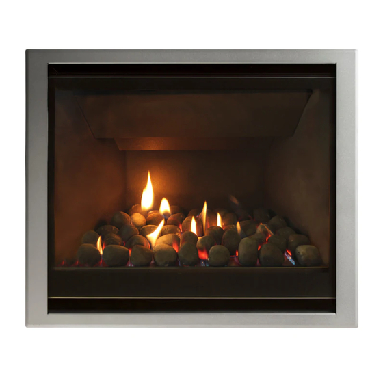
Page 37: E12 Flame Picture
An abnormal flame pattern will likely be the result of incorrect settings (jet size, burner aeration collar, flue restriction), and if present you must check these are correct before proceeding. If an abnormal flame pattern is still present, please contact Escea. It is the responsibility of the installer to ensure a correct flame pattern. -
Page 38: E15 Installing The Glass
DF960 Log Layout Use the index below as a guide for selecting the correct logs: E15 Installing the Glass Refer to section D2 and reverse the steps. -
Page 39: E16 Home Automation Setup
µ From Automation system Connector and terminal block supplied by Escea Note: you will need to match the relay coil voltage with the volt- age from your automaton system. The Home Automation connection can be found to the right of the electronics tray (for access instructions see section E3). -
Page 40: Fitting The Fascia And Finishing Installation
A suitable distance away from the heater. Ideally 1.2m to 1.5m from the floor The radio frequency signal will go through some walls but for best results Escea suggest that the cradle position is between 1 and 5 metres away from the heater. -
Page 41: F3 Operating The Appliance For The First Time
Operating the Appliance for the First Time Remove the battery cover on the rear of the remote. Insert the new “AA” size batteries, paying atten- tion to the polarity. You should now see on the display of the remote the time showing “0:00”. To turn the fire on, press the “POWER”... -
Page 42: F4 Normal Operating Sounds And Smells
• Fan: Escea gas appliances use electric fans to push heated air further into the room. It is not un- usual for the fan to make a “whirring” sound when ON. This sound will increase or decrease in volume depending on the speed setting of your fan. -
Page 43: Freestanding Unit (Dfs730) Installation
Freestanding Unit (DFS730) Installation Product Dimensions 735mm* 124mm *Not including Lid Overhang 505mm 381mm 368mm* 368mm* 753mm G2 Hearth and Clearances A Hearth is not required, however it may be used for decorative purposes or for protection of sensitive flooring. The hearth should not obscure the air inlet of the fire. Do not place items or furnishings ontop of the freestanding fireplace, and ensure soft furnishings do not come in contact with the freestanding fireplace. -
Page 44: G4 Gas Pipe Routing Information
G4 Gas pipe Routing Information... -
Page 45: G5 Flue Installation
G5 Flue Installation The freestanding unit and flue system should be installed prior to the DF-Series fireplace being installed (for horizontal termination for DFS730: see next page, section G6). □ Place the freestanding unit in the correct location, complying with Rigid ue the clearances specified in the previous section. -
Page 46: G6 Horizontal Flue Kit
Note: Instructions for installation are provided with the kit DF700 Fireplace installation into DFS730 Freestanding Unit Once the freestanding unit is in place, and the flue system installed, the DF700 fireplace installation can commence. Note: for the Apartment Flue Kit, see the instructions provided with the kit. -
Page 47: H Installation Checklist
Installation Checklist Go through the following checklist to ensure you have installed the appliance correctly □ Correctly sized cavity to suit your fascia and flue configuration □ Correct clearances to combustibles and mantles around the fascia □ An electrical isolating switch to the appliance, accessible after finished installation □... -
Page 48: S Service Manual
Service Manual IMPORTANT: • This appliance must be serviced every 12 months. • Any service operation should be carried out only by a suitably qualified and trained person. • Gas and electricity supply MUST be isolated before any service operation is carried out on this appliance. -
Page 49: S2 Serial Number
The bimetallic snap disk mounted on the back chassis panel has tripped. The possible causes for this could include: • Fascia may be installed incorrectly resulting in restricted air flow. • The room air fan may be slowed or stalled. Remove firebox, check that Appliance Over the fan is plugged in, cleaned, and free turning. -
Page 50: S3 Checking Operating Pressure
NEVER RUB THE FASCIA. The outside of the fascia’s must only be cleaned with a clean damp cloth, dry off after cleaning. The high temp silver powder coating that is used on Escea fascia parts contains certain amounts of aluminium that when rubbed too hard will oxidise leaving a black smudge that cannot be removed. -
Page 51: S7 Removing The Electronic Tray
DF960 Fan Screw Locations Removing Electronic Tray ISOLATE THE POWER TO THE FIRE BEFORE THIS PROCEDURE. All of the electronic components of the heater have been located on a removable tray. Remove the 18-way connector & 6-way connector from the end of the tray, the network cable, if installed (both locations circled in diagram below) and the transformer connector located in the rear LH corner of the electronics tray. -
Page 52: S8 Replacing The Thermal Cut Out
Replacing the Thermal Cut Out Once the screw is removed from below the stepped firebox baffle, gently lift the baffle up and bring towards you. Remove the 8 machine screws in the access panel (as shown in the diagram below). -
Page 53: S9 Removing The Pressure Switch
Remove the 2 machine screws from the TCO bracket (as shown in the diagram below) Disconnect the two wires from the TCO and the bracket with the TCO may then be removed from the fire box for replacement. Removing the pressure switch Remove the two machine screws located in the rear RH side of the firebox to detach the pressure switch bracket. -
Page 54: S10 Replacing A Remote
If the remote becomes lost or damaged, a new one can be ordered from any Escea retail agent. When you have the new remote, the following procedure needs to be followed to “teach” the remote to only communicate with that fire. -
Page 55: S11 Annual Service Procedure
S11 Annual service procedure □ Isolate power and gas supply to fire. □ Remove front glass and clean inside of glass. □ Remove fuel bed and brush off any soot. □ Clean electrode and pilot hood of any carbon build up and ensure correct gaps between electrode and pilot hood □... -
Page 56: S12 Wiring Diagram
S12 Wiring Diagram...
Need help?
Do you have a question about the DF700 and is the answer not in the manual?
Questions and answers