Table of Contents
Advertisement
Available languages
Available languages
Quick Links
IMPORTANT INSTRUCTIONS -
Models: ES80S, ES130S,
ES80D, ES130D
READ AND SAVE THESE INSTRUCTIONS
READ CAREFULLY BEFORE ATTEMPTING TO ASSEMBLE, INSTALL, OPERATE OR MAINTAIN THE PRODUCT DESCRIBED.
PROTECT YOURSELF AND OTHERS BY OBSERVING ALL SAFETY INFORMATION. FAILURE TO COMPLY WITH
INSTRUCTIONS COULD RESULT IN PERSONAL INJURY AND/OR PROPERTY DAMAGE!
GENERAL SAFETY INFORMATION
electric shock and injury to person, including the following:
WARNING:
TO REDUCE THE RISK OF FIRE, ELECTRIC
SHOCK AND INJURY TO PERSON, OBSERVE THE FOLLOWING:
a) Use this unit only in the manner intended by the manufacturer.
If you have questions, contact the manufacturer.
b) Before servicing or cleaning the unit, switch power off at
service panel and lock the service disconnecting means to
prevent power from being switched on accidentally. When
the service disconnecting means cannot be locked, securely
fasten a prominent warning device, such as a tag, to the
service panel.
WARNING:
TO REDUCE THE RISK OF FIRE, ELECTRIC
SHOCK AND INJURY TO PERSON, OBSERVE THE FOLLOWING:
a) Installation work and electrical wiring must be done by
qualified person(s) in accordance with all applicable codes
and standards, including fire-related construction.
b) Sufficient air is needed for proper combustion and exhausting
of gases through the flue (chimney) of fuel burning equipment
to prevent back drafting. Follow the heating equipment
manufacturer's guideline and safety standards such as those
published by the National Fire Protection Association (NFPA)
and the American Society for Heating, Refrigeration, and Air
Conditioning Engineers (ASHRAE), and the local code authorities.
c) When cutting or drilling into wall or ceiling, do not damage
electrical wiring and other hidden utilities.
A210572218 New 7-09
OPERATING MANUAL
RETAIN INSTRUCTIONS FOR FUTURE REFERENCE.
When using electrical appliances, basic precautions
should always be followed to reduce the risk of fire,
SAVE THESE INSTRUCTIONS
d) Ducted fans must always be vented to the outdoors.
e) If this unit is to be installed over a tub or shower, it must be
marked as appropriate for the application and be connected
to a GFCI (Ground Fault Circuit Interrupter) - protected branch
circuit.
f) This unit must be grounded.
g) To avoid motor bearing damage and noisy and/or unbalanced
impellers, keep drywall spray, construction dust, etc. off
power unit.
h) NEVER place a switch where it can be reached from a tub
or shower.
i) Suitable for use with electronic speed control device.
j) Do not install into ceilings thermally insulated to a value
greater than R40.
CAUTION:
NOT USE TO EXHAUST HAZARDOUS OR EXPLOSIVE MATERIALS
AND VAPORS.
WARNING:
k) Read all instructions before installing or using exhaust fan.
www.airkinglimited.com
Exhaust Fan
FOR GENERAL VENTILATING USE ONLY. DO
DO NOT USE IN KITCHENS.
1 of 12
Advertisement
Table of Contents

Related Manuals for Air King ES80S


Summary of Contents for Air King ES80S
-
Page 1: General Safety Information
IMPORTANT INSTRUCTIONS - OPERATING MANUAL Models: ES80S, ES130S, Exhaust Fan ES80D, ES130D READ AND SAVE THESE INSTRUCTIONS READ CAREFULLY BEFORE ATTEMPTING TO ASSEMBLE, INSTALL, OPERATE OR MAINTAIN THE PRODUCT DESCRIBED. PROTECT YOURSELF AND OTHERS BY OBSERVING ALL SAFETY INFORMATION. FAILURE TO COMPLY WITH INSTRUCTIONS COULD RESULT IN PERSONAL INJURY AND/OR PROPERTY DAMAGE! RETAIN INSTRUCTIONS FOR FUTURE REFERENCE. -
Page 2: Installation Instructions
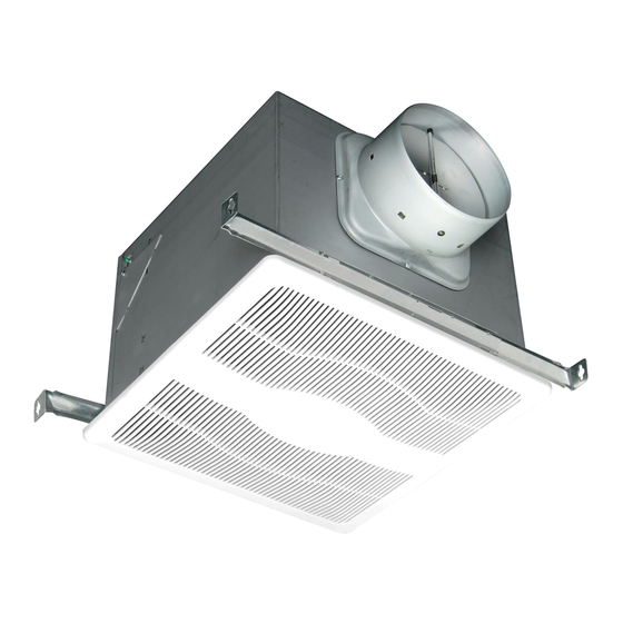
INSTALLATION INSTRUCTIONS Bracket CAUTION: MAKE SURE POWER IS SWITCHED OFF AT SERVICE PANEL BEFORE STARTING INSTALLATION. SECTION 1 Housing Preparing the Exhaust Fan 1. Unpack fan from the carton and confirm that all pieces are present. In addition to the exhaust fan you should have: 1 - Grill 1 - Damper Assembly (attached) Header Figure 3 2 - Mounting Brackets 4 - #10-32 Nuts SECTION 3 1 - Instruction/Safety Sheet Ducting 2. Choose the location for your fan. To ensure the best air and sound CAUTION: performance, it is recommended that the length of ducting and the ALL DUCTING MUST COMPLY WITH LOCAL AND number of elbows be kept to a minimum, and that insulated hard... - Page 3 (not included), connect the Black wire (Hot) from the power source Wire Compartment to the 1C (common terminal) on the switch. Connect the Black wire Cover of the fan to the 1A terminal on the switch and connect a jumper Screw from the 1A to the 1b terminal. Connect the White (Neutral) wire from the power source to the white wire on the fan. Connect one of the two yellow wires from the fan to terminal 2C of the switch. Connect the other yellow wire to terminal 2B of the switch. Placing the toggle in the B position will energize high Figure 7 speed placing the toggle in the center position will turn the fan off and placing the toggle in the a position change the fan to low speed. Connect the ground wire from the house to the SINGE SPEED UNITS (models ES80S and ES130S) green wire from the fan housing (Figure 10). 2a. Run wiring from an approved wall switch (not included) carrying the appropriate rating. One neutral (white), one ground (green or Supply from house White bare copper), and one hot (black lead connected to the switch). Secure the electrical wires to the housing with an approved Ground electrical connector. Make sure you leave enough wiring in the box to make the connection to the fan’s receptacle. Hot (Black) 2b. From where you have chosen to access the fan’s junction box, connect the white wire from the house to the white wire from the Yellow fan’s receptacle. Connect the black wire from the wall switch to the black wire from the fan’s receptacle. Connect the ground wire from the house to the green wire from the fan housing (Figure 8).
-
Page 4: Troubleshooting Guide
quick connect motor cord into the receptacle located on the top 4. Install the grill by squeezing the two ends of the springs together of the wire compartment cover These cords will only fit one way and installing them up into the slots on the fan’s housing. Push into the receptacles (Figure 11). the grill up into position (Figure 13). Figure 11 Figure 13 TWO SPEED UNITS (models ES80D and ES130D) 3. Plug the fan’s 2 pin quick connect motor cord and the 3 pin quick 5. Restore power and test your installation. connect motor cord into the receptacles located on the top of the wire compartment cover. These cords will only fit one way into the receptacles (Figure 12). SECTION 6 Use and Care CAUTION: MAKE SURE POWER IS SWITCHED OFF AT SERVICE PANEL BEFORE SERVICING THE UNIT. 1. Cleaning the Grill: Remove grill and use a mild detergent, such as dishwashing liquid, and dry with a soft cloth. NEVER USE ANY ABRASIVE PADS OR SCOURING POWDERS. Completely dry grill... -
Page 5: Limited Warranty
ONE YEAR FROM THE DATE OF ORIGINAL PURCHASE OR UNTIL THE ORIGINAL PURCHASER OF THE PRODUCT SELLS OR TRANSFERS THE PRODUCT, WHICHEVER FIRST OCCURS AND IN NO EVENT SHALL AIR KING’S LIABILITY UNDER ANY EXPRESS OR IMPLIED WARRANTY INCLUDE (I) INCIDENTAL OR CONSEQUENTIAL DAMAGES FROM ANY CAUSE WHATSOEVER, OR (II) REPLACMENT OR REPAIR OF ANY HOUSE FUSES, CIRCUIT BREAKERS OR RECEPTACLES. -
Page 6: Replacement Parts Diagram
REPLACEMENT PARTS DIAGRAM ES80S ES130S ES80D ES130D # Qty. Description Replacement Part # # Qty. Description Replacement Part # 1 Fan Housing 5S1202044 21 1 Wire Compartment Assembly - ES80S 5S1239001 2 Mounting Bar 5S1202045 22 1 Wire Compartment Assembly - ES130S 5S1239002 3 Hex Nuts 5S1202041 A 1 Wire Compartment 5S1239003 4 6” Metal Collar Assembly... -
Page 7: Ventilateur D'évacuation
INSTRUCTIONS IMPORTANTES – MODE D’EMPLOI Modéles : ES80S, ES130S, Ventilateur d’Évacuation ES80D, ES130D LIRE ET CONSERVER CES INSTRUCTIONS LIRE SOIGNEUSEMENT AVANT DE TENTER D’ASSEMBLER, INSTALLER, OPÉRER OU DE RÉPARER LE PRODUIT DÉCRIT. PROTÉGEZ VOUS-MÊME ET LES AUTRES EN OBSERVANT TOUTE L’INFORMATION DE SÉCURITÉ. FAILLIR À SE CONFORMER AUX INSTRUCTIONS PEUT RÉSULTER EN BLESSURE PERSONNELLE GRAVE ET/OU EN DOMMAGE À... -
Page 8: Instructions D'installation
INSTRUCTIONS D’INSTALLATION Support AVERTISSEMENT : VOUS ASSURER QUE L’ALIMENTATION EST COUPÉE AU PANNEAU DE SERVICE AVANT DE COMMENCER L’INSTALLATION. Châssis SECTION 1 Préparation du Ventilateur d’évacuation Écrou 1. Sortir le ventilateur de sa boite et confirmer que toutes les pièces sont présentes. En plus du ventilateur d’évacuation vous devriez avoir : 1 - Grille Chevêtre Figure 3 1 - Ensemble de clapet (attaché) 2 - Supports de montage SECTION 3 4 - Écrous 10-32 Conduits 1 - Feuillet d’instructions / sécurité... - Page 9 Couvercle du Reliez le fil noir du ventilateur à la borne 1A sur le commutateur et Compartiment reliez une bretelle du 1A à la borne 1B. Reliez le fil (neutre) blanc de de Câblage la source d’énergie au fil blanc sur le ventilateur. Reliez un des deux fils jaunes du ventilateur à la borne 2C du commutateur. Reliez l’autre fil jaune à la borne 2B du commutateur. Le placement du bouton dans la position de B activera la vitesse. Le placement du bouton dans la position centrale arrêtera le ventilateur et le placement du bouton dans la position A changera le ventilateur Figure 7 à une vitesse réduite. Reliez le fil de terre de la maison au fil vert du logement du ventilateur (Figure 10). UNITÉS À UNE VITESSE (modéles ES80S et ES130S) 2a. Posez le câblage d’un commutateur mural approuvé (non inclus) Alimentation provenant portant la spécification appropriée. Un neutre (blanc), un de terre de la résidence Blanc (vert ou cuivre dénudé), et un chaud (fil de sortie noir relié au commutateur). Fixez les fils électriques au logement avec une prise Fil de Masse électrique approuvée. Assurez-vous de laisser assez de câblage dans la boîte pour faire la connexion au réceptacle du ventilateur. 2b. De l’endroit où vous avez choisi d’accéder à la boîte de raccordement du ventilateur, reliez le fil blanc de la maison au fil blanc du Jaune réceptacle du ventilateur. Reliez le fil noir du commutateur mural Ventilateur au fil noir du réceptacle du ventilateur. Reliez le fil de terre de la...
-
Page 10: Utilisation Et Entretien
du ventilateur située sur le dessus de la couverture du compartiment 4. Installer la grille en pressant ensemble les deux extrémités des du fil. Ces cordes s’inséreront seulement d’une façon dans les ressorts et en les installant dans les fentes du châssis du ventilateur. réceptacles (Figure 11). Pousser la grille en position (Figure 13). Figure 11 Figure 13 UNITÉS À DEUX VITESSES (modéles ES80D et ES130D) 3. Branchez la corde à 2 broches à connexion rapide du moteur du 5. Restaurer l’alimentation et tester votre installation. ventilateur située et la corde à 3 broches à connexion rapide du moteur du ventilateur dans les réceptacles situés sur le dessus de la couverture du compartiment du fil. Ces cordes s’inséreront SECTION 6 seulement d’une façon dans les réceptacles (Figure 12). Utilisation et entretien AVERTISSEMENT : VOUS ASSURER QUE L’ALIMENTATION EST COUPÉE AU PANNEAU DE SERVICE AVANT DE COMMENCER L’INSTALLATION. -
Page 11: Garantie Limitée
AN DE LA DATE DE L’ACHAT ORIGINAL OU JUSQU’À CE QUE L’ACHETEUR ORIGINAL DU PRODUIT VEND OU TRANSFÈRE LE PRODUIT, CELUI QUI SE PRODUIT EN PREMIER ET DANS AUCUN CAS AIR KING N’ASSUME AUCUNE RESPONSABILITÉ EXPRESSE OU TACITE POUR (I) DES DOMMAGES ACCIDENTELS OU INDIRECTS DE N’IMPORTE QUELLE CAUSE, OU (II) LE REPLACEMENT OU LA RÉPARATION DE TOUS FUSIBLES, DISJONCTEURS OU RÉCEPTACLES DE MAISON. - Page 12 DIAGRAMME DES PIÈCES DE REMPLACEMENT ES80S ES130S ES80D ES130D # de pièce # de pièce # Qté. Description de remplacement # Qté. Description de remplacement 1 Cabinet du ventilateur 5S1202044 21 1 Assemblée du compartiment du fil - ES80S 5S1239001 2 Barre de montage 5S1202045 22 1 Assemblée du compartiment du fil - ES130S 5S1239002 3 Écrou 5S1202041 A 1...
Need help?
Do you have a question about the ES80S and is the answer not in the manual?
Questions and answers