Table of Contents
Advertisement
Quick Links
(These instructions are intended for use by a technician familiar with electronic products)
RM-10012 /RM-10012M are continuous duty 13.8 VDC
output power supply with,
80% efficiency
Thermostatically controlled fans
Selectable 110 or 220 VAC inputs
Modular design provides "N + 1" redundancy
Adjustable output voltage
Optional metering for voltage & current
GENERAL SPECIFICATIONS
Output Voltage .................................................................................................................................................................................................. 13.8 V
Output Voltage Tolerance ............................................................................................................................................................................... +/- 1 pct
Output amperage, max continuous ....................................................................................................................................................................... 72 A
Maximum Output Amperage .......................................................................................................................................................... Single Surge 100 A
Maximum Power, continuous ..................................................................................................................................................................... 1000 Watts
Output Voltage Adjustment .................................................................................................................................................................. +10 pct, -15 pct
Maximum ripple and noise .................................................................................................................................. 150 mV p-p max, 10 mV RMS typical
Input voltage range (switch selectable) ................................................................................................................................... 90-130 or 180-280 VAC
Input frequency range .................................................................................................................................................................................... 47-63 Hz
Maximum AC current ....................................................................................................................................................... 15 A/120 VAC; 8 A/240 VAC
Typical Efficiency ................................................................................................................................................................................................ 80 pct
Max inrush current, single cycle ............................................................................................................................................................................ 35 A
Short Circuit protection ..................................................................................................................................................................... Foldback Limiting
Overload Protection (operates) ....................................................................................................................................................... typical 110-120 pct
Line Regulation ................................................................................................................................................................................................. 50 mV
Load Regulation ................................................................................................................................................................... 100 mV (20-100 pct load)
Fan Control........................................................................................................................................................... Heat sink temp >140 F (60 C) = ON
Over Temperature ............................................................................................................................................... >195 F (90 C) auto output shutdown
Rise Time following ON ..................................................................................................................................................................................... 50 mS
Hold Time following OFF ................................................................................................................................................................................... 10 mS
Working Temperature range ...................................................................................................................................................... 32 - 125 F (0 - +50 C)
Storage Temperature ............................................................................................................................................................... 0 - 185 F (-20 - +85 C)
Withstand Voltage* ......................................................................................................................................... 1.5 KV @ 10 ma(I/P-O/P, I/P-FG)/1 min
(Continued) .................................................................................................................................................... 500 V @ 10 ma(O/P-FG)/1 min
Dimensions........................................................................................................................................................ 7.0 H x 19 W x 7.5 D inches, nominal
Weight .................................................................................................................................................................................................. 13 lbs, nominal
GENERAL APPLICATION NOTES
The RM-series is constructed using SM-series modules. Input and output connections of the SM-series are via a 9 place screw type barrier terminal
strip.
Connection Labels and Meaning / Use. Starting from the left:
L .......................................................................................................................................... Line Input in 120 VAC systems or A leg in 240 VAC
N ................................................................................................................................. System Neutral in 120 VAC systems or B leg in 240 VAC
FG ............................................................................................................................................ Chassis or frame ground (system safety ground)
NC ................................................................................................................................................................................................ No Connection
P ........................................................................................................................................ Parallel Connection feed back, unit to unit load share
-V ............................................................................................................................................................................... Negative Output terminals
+V ................................................................................................................................................................................ Positive Output terminals
V ADJ ........................................................................................................................................................................ Output Voltage Adjustment
Green LED ......................................................................................................................................................................... Output Indicator LED
WARNINGS
The individual user should take care to determine, prior to use or installation, whether this device is suitable, adequate or safe for the use intended.
Since individual applications are subject to great variation, DuraComm makers no representation or warranty as to the merchantability, suitability or
fitness of these units for any specific application.
The precision regulated power supplies operate internally from voltages in excess of 12/24/48 volts. In rare cases, voltage spikes or transients on the
AC power line, or over heating, may cause a component failure in the power supply. Overloading the output will cause the over current feature to
operate. In either case, the cause must be determined and corrected.
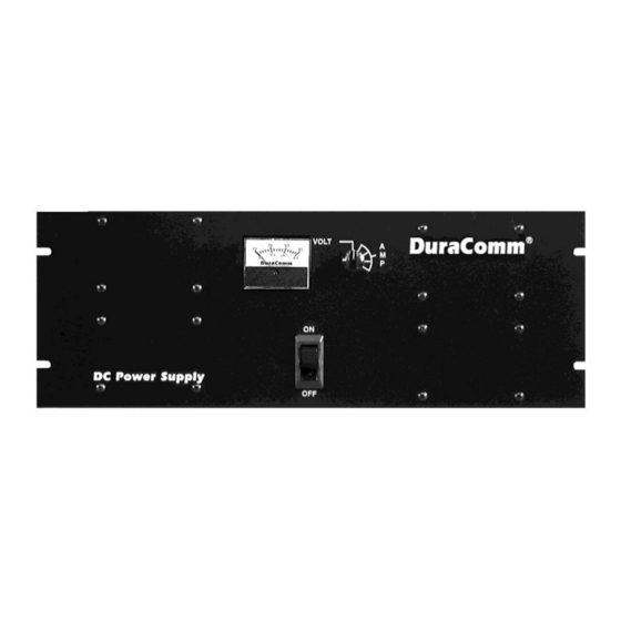
DuraComm
RM-10012 / RM-10012M
Heavy Duty AC to DC Power Supply
USER GUIDE
Advertisement
Table of Contents

Related Manuals for DuraComm RM-10012


Summary of Contents for DuraComm RM-10012
-
Page 1: General Specifications
The individual user should take care to determine, prior to use or installation, whether this device is suitable, adequate or safe for the use intended. Since individual applications are subject to great variation, DuraComm makers no representation or warranty as to the merchantability, suitability or fitness of these units for any specific application. - Page 2 BATTERY BACK-UP INSTALLATIONS DuraComm has a battery backup accessory, Model RMBC, for the RM-series of power supplies. The RMBC mounts directly to the rear panel of the RM-series and provides auto-change to battery power. Model RMBC provides a trickle charge to the battery. Do NOT connect a lead-acid battery...
-
Page 3: Limited Warranty
DuraComm reserves the right to change, alter, or improve the specifications of its products at any time, and by so doing, incurs no obligation to install or retrofit any such changes or improvements in or on products manufactured prior to inclusion of such changes.
Need help?
Do you have a question about the RM-10012 and is the answer not in the manual?
Questions and answers