Table of Contents
Advertisement
Quick Links
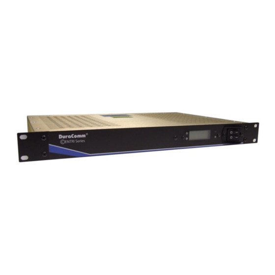
With Battery Back-Up and Low Voltage Disconnect
Output Amperage
Output Voltage
Input Voltage Range
Charging Current
Suggested Battery Capacity
Disconnect / Reconnect
Product Dimensions
Shipping Dimensions
Shipping Weight
*intended to be used with external charger to support large Ah battery banks. Battery charging depends on
battery size and charger.
*NOTE: Specifications are subject to change without notice.
©entri Series
HE1U-XX12-BBLVD-MU
High-Efficiency Low Profile 12V Power Supply
Model
HE1U-2012-BBLVD-MU
20 Amps
•
•
•
•
•
•
•
HE1U-5012-BBLVD-MU
50 Amps
13.8 VDC
90 – 264 VAC Auto-Ranging
External Battery Charger Required*
Based on Battery Charger or Application*
10.0 / 12.5 VDC
19 x 14 x 1.75 in, 19" Rack Mount 1U Height
21 x 15 x 8 in
12 lbs.
Internet ready
Front panel display
Integrated low voltage battery
disconnect
Remote monitoring of voltage, current,
temperature, and external alarm
Remote control of power supply,
battery connection, and alarm output
via web interface
Configurable alarms, email
notifications, and SNMP traps
Manual battery disconnect switch
HE1U-12012-BBLVD-MU
100 Amps
Edit: Nov. 21, 18
Advertisement
Table of Contents

Related Manuals for DuraComm HE1U Series


Summary of Contents for DuraComm HE1U Series
- Page 1 ©entri Series HE1U-XX12-BBLVD-MU High-Efficiency Low Profile 12V Power Supply With Battery Back-Up and Low Voltage Disconnect • Internet ready • Front panel display • Integrated low voltage battery disconnect • Remote monitoring of voltage, current, temperature, and external alarm • Remote control of power supply, battery connection, and alarm output via web interface...
-
Page 2: Table Of Contents
Front Panel Control ........................4 Rear Panel Wiring .......................... 5 Rear Connectors ..........................5 Connecting to the DuraComm Unit VIA the Internet ............... 6 Prerequisites ..........................6 Determining the IP Address of the Unit ..................6 Using DHCP ..........................6 Using Static IP and Network Configuration .................. -
Page 3: Section 1 | Important Safety Instructions
NOTE: The individual user should take care to determine prior to use or installation whether this device is suitable, adequate, and safe for the use intended. Since individual applications are subject to numerous variations, DuraComm makes no representation or warranty as to the merchantability, suitability, or fitness of these units for any specific application. -
Page 4: Conductor Pretreatment
Conductor Pretreatment All kinds of copper conductors can be clamped without treatment. DO NOT solder tin stranded conductors. The solder yields and fractures under high pressure. The result is increased contact resistance and excessive temperature rise. Additionally, corrosion has been observed due to the fluxes. -
Page 5: Rear Panel Wiring
Rear Panel Wiring This system setup will provide continuous power to the load and maintain the battery bank with the smart charger while AC power is on. There is a seamless transfer of the load to the battery when the AC power goes off. -
Page 6: Connecting To The Duracomm Unit Via The Internet
192.168.100.220, gateway address: 192.168.100.1, netmask: 255.255.255.0, and DNS address: 192.168.100.1. If you configure it to use DHCP, the DuraComm internet-ready unit will request an available IP address on your network. You will need to determine what address it has been given. -
Page 7: Open A Web Connection To The Unit
Open a Web Connection to the Unit 1. Connect the RJ-45 connector on the back of the DuraComm unit to your network. 2. Use your favorite device and browser (Chrome, Firefox, Internet Explorer, etc.), and enter the IP address of the power supply on your network into the URL box on the browser (see the screenshot below). -
Page 8: Section 4 | Remote Monitoring And Control Setup
“remote control unit PCB and hold it for more than 30 seconds (you will need to remove the cover on the DuraComm unit, and connect power to the battery terminals). Re- connect to the unit through your web browser by entering the factory supplied IP address and HTTP port (see Network Setup). -
Page 9: User Login
Figure 6. User login pop-up window prompting user name and password. Enter the username and password. The “Admin” and “Control” are the only two users pre-configured in a DuraComm internet-ready unit. Factory default username and password are as follows: “Admin” users have full user control of the device. -
Page 10: Network Setup
80. If a different HTTP port is used, it will need to be added to the URL to access the DuraComm unit. For example: if the port is changed to 8080 then the address would be changed to http://192.168.0.253:8080... -
Page 11: Email Setup
Email Setup Figure 8. Email setup page. Enter the required email setup parameters given to you by your System Administrator. You can also send a test email from this screen. Sending Text Messages In order to send a text, you need to send an email to the appropriate email address of your cell phone carrier. -
Page 12: Device Setup
A custom site name can be entered here, and the model, serial number, hardware and firmware version are shown here. The DuraComm internet-ready unit will log all measurements and alarms to an SD card that is plugged in on-board. Users can set the logging rate, as well as clear the card, or append new measurements. -
Page 13: Sensor Setup
Inputs and outputs of the DuraComm internet-ready unit are wired as shown on the Sensor Setup screen. The user can enter text to change the user meaning of the digital output states, and there are 3 color options for the buttons. -
Page 14: Alarm Setup
Figure 11. Analog, Temperature, AC, and Digital alarm setup. In a DuraComm internet-ready unit, the analog alarms can be set by selecting the drop-down menu next to the “Analogs” label. As shown in the figure, the “Amps Power Supply” is currently selected. -
Page 15: Default Analog Alarm Settings
A simplified version of the status page is available for mobile devices. Just use the same IP address and add ‘/m’. For example, 192.168.100.220/m Note: These screenshots are taken from a DuraComm internet-ready MU series and are shown typical setup information for all model numbers in the series (except for the model number). -
Page 16: Section 5 | Specifications
Section 5 | Specifications Models HE1U-2012-BBLVD-MU HE1U-5012-BBLVD-MU HE1U-12012-BBLVD-MU Output DC Voltage 13.8 VDC Maximum Output Current 20 Amps 50 Amps 100 Amps Maximum Power, continuous 330 Watts 750 Watts 1500 Watts Maximum Ripple and Noise 150 mV p-p 150 mV p-p 150 mV p-p Voltage Tolerance ±... -
Page 17: Section 6 | Warranty
DuraComm reserves the right to change, alter, or improve the specifications of its products at any time, and by so doing, incurs no obligation to install or retrofit any such changes or improvements in or on products manufactured prior to inclusion of such changes.
Need help?
Do you have a question about the HE1U Series and is the answer not in the manual?
Questions and answers