Table of Contents
Advertisement
Quick Links
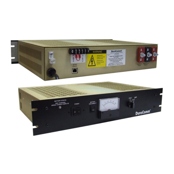
Internet Ready Heavy Duty AC to DC Power Supply
With Built-in Remote Monitoring and Control.
(These instructions are intended for use by a technician familiar with electronic products)
Internal Remote Monitoring and Control Unit
Web Ready / Web GUI
Smart Charger
Monitor Voltages, Power Supply Current, Battery Current
and Alarms
Remote Shutdown of Each Power Supply Module
Alarm IN and Alarm Out
Battery backed up Real Time Clock to Timestamp Logged
Information.
Monitoring Samples can be Logged and Downloaded
Input Voltage 88 to 132 VAC, 176 to 264 VAC Switch
Selectable
Analog Metering: Load Voltage / Each Power Supply
Amperage
Short Circuit / Overload / Over Voltage / Over Temperature
Protection
Manual Battery Disconnect Switch
Designed for Negative Ground Applications Only
3 year warranty
DESCRIPTION
The RLP-2024BBSCLVD-MU is a Heavy Duty AC to DC Power Supply with smart charger that is web ready for remote
monitoring and control. The new internal Remote Monitoring and Control Unit (RMCU), provides the ability to remotely monitor the AC
voltage, battery voltage, power supply voltage for each module, power supply current for each module, battery current, LVD status,
external alarm status, as well as the ability to remotely control the state of each power supply module, all via the internet using any
standard web browser. A mobile friendly version of the status page is included, and an alarm output is also provided.
Users that have access to the network can view the status of the power supply, control outputs, and the alarm conditions, as
well as download a .CSV file of logged states. Administrative users can access the setup screens and change the control settings by
logging into the RLP-2024BBSCLVD-MU via the browser. Alarm conditions are configurable, and can include over and under
thresholds and discreet logical inputs. Notifications via email can also be configured to notify an administrator. Setups are saved in non-
volatile RAM, and a battery backed up real-time clock is provided to timestamp information logged to the internal SD card. Logging rate
is user settable.
This power supply comes with power factor correction, and with front panel metering for voltage and current. All of the RLP
series come with four layers of protection against overload, over voltage, over temperature, and short circuit protection. This model also
comes with a manual battery disconnect.
The RLP-2024BBSCLVD-MU comes with the DuraComm three-year warranty.
RLP-2024BBSCLVD-MU
Owners Guide
1 of 21
January 25, 2017
Advertisement
Table of Contents

Related Manuals for DuraComm RLP-2024BBSCLVD-MU


Summary of Contents for DuraComm RLP-2024BBSCLVD-MU
- Page 1 DESCRIPTION The RLP-2024BBSCLVD-MU is a Heavy Duty AC to DC Power Supply with smart charger that is web ready for remote monitoring and control. The new internal Remote Monitoring and Control Unit (RMCU), provides the ability to remotely monitor the AC...
-
Page 2: Specifications
SPECIFICATIONS Output Voltage ..................................27.6 VDC Output Voltage Tolerance ................................+/- 1 % Output Amperage ................................23 Amps cont. Maximum Power, continuous ..............................648 Watts Maximum Ripple and Noise ............................150 mV p-p max Input Voltage (Switch Selectable) ......................88 to 132VAC, 176 to 264 VAC Input Frequency Range ................................ -
Page 3: Installer Notes
Physical mounting position is not critical but the cooling vents must not be blocked. NOTE: The outputs are NOT referenced to the chassis, however the Alarms are referenced the power supply and battery ground. The RLP-2024BBSCLVD-MU is designed for negative ground application only. 3 of 21... -
Page 4: Installation Block Diagram
NOTE: The ‘G’ connection on the alarm terminal strip is the same as Power Supply and Battery Negative, so the RLP- 2024BBSCLVD-MU is not designed for Positive Ground applications. The RJ-45 connects the RLP-2024BBSCLVD-MU to your 10/100 Ethernet network. 4 of 21... -
Page 5: Using Dhcp
If your network is not set up for DHCP, you will need to manually configure the settings to match the network it will be used on. Before you can do that, you will need to configure a computer to talk to the RLP-2024BBSCLVD-MU at the default configuration settings shown above. - Page 6 USB connection to access the device and configure the IP address. If the RLP-2024BBSCLVD-MU responds with the “Status” screen, then skip to the User Login Section.
-
Page 7: User Login
REMOTE MONITORING AND CONTROL (RMCU) SETUP All setup requires an administrative user to log into the RMCU in your power supply. Click the ‘Login’ button in the top menu. User Login Enter the user name and password. Factory default username and password are as follows: Admin Users have full control of the device. -
Page 8: Network Setup
NETWORK SETUP 8 of 21 January 25, 2017... - Page 9 The MIB file for the RLP-2024BBSCLVD-MU can be downloaded from the RLP-2024BBSCLVD-MU after you connect to it with your browser. Go to the Device Setup page and log in to the RLP-2024BBSCLVD-MU. Halfway down the page there is a link to the MIB file. Right click on the link and click “Save Link As” to download the file.
-
Page 10: E-Mail Setup
EMAIL SETUP Email Setup Enter the required email setup parameters given to you by your System Administrator. You can also send a test email from this screen. Firmware revision 2.7 added the ability to send periodic status or “heartbeat” emails. Enter the number of minutes between status emails. -
Page 11: Device Setup
DEVICE SETUP 11 of 21 January 25, 2017... -
Page 12: Device Info
Logging The RLP-2024BBSCLVD-MU will log all measurements and alarms to an SD card that is plugged into the RMCU board. Users can set the rate here, as well as clear the card, or append new measurements. The CSV log file can be downloaded here, as well as the Status page. -
Page 13: Sensor Setup
SENSOR SETUP 13 of 21 January 25, 2017... - Page 14 #1 thru #4 are the only ones wired and configured in the RLP-2024BBSCLVD-MU. In the RLP-2024BBSCLVD-MU the Digital Output 1 is an alarm output, and Digital Output 2 controls the ON/OFF state of the power supply. The user must be logged in as the admin or control user to control the digital outputs. The digital outputs can be controlled by the buttons on the status page, mobile page, or via SNMP on the RLP-2024BBSCLVD-MU Optionally, they can be automatically controlled by connecting them to an alarm on the “Alarms”...
-
Page 15: Alarm Setup
ALARM SETUP 15 of 21 January 25, 2017... - Page 16 Alarm Setup This screen is for setting up analog and digital alarms. To set up analog alarms, first you must select the alarm channel to set. This is accomplished by selecting the custom name of the channel in the dropdown box next to the “Analogs” label. For example, we are looking at the settings for the “Module #1 Amps”...
-
Page 17: User Setup
USER SETUP User Setup Password changes and RMCU hard resets are perform by using this page. Care should be taken when changing any of these settings. NOTE: To hard reset your device back to factory settings, press the red button on the RMCU PCB and hold it for more than 20 seconds. -
Page 18: Status Screen
REMOTE MONITORING AND CONTROL STATUS PAGE Status screen This screen shows the status of all analog and digital inputs, as well as digital outputs. A user can also download the Log file from this page. AC Voltage is approximate. The admin or Control user must be logged in to control the digital outputs. 18 of 21 January 25, 2017... - Page 19 Mobile Status Screen A simplified version of the status page is available for mobile devices. Just use the same IP address and add ‘/m’. for example 192.168.100.220/m RMCU MAINTENANCE Battery The battery on the RMCU is used to back up the real time clock for logging purposes. Logged in users can see the current system time on the Device Setup page under Date and Time settings.
- Page 20 CONDUCTOR PRETREATMENT All kinds of copper conductors can be clamped without treatment. DO NOT solder tin stranded conductors. The solder yields and fractures under high pressure. The result is increased contact resistance and excessive temperature rise. Additionally, corrosion has been observed due to the fluxes. Notch fractures at the transition from the rigid tinned part to the flexible conductors are also possible.
-
Page 21: Limited Warranty
DuraComm reserves the right to change, alter, or improve the specifications of its products at any time, and by so doing, incurs no obligation to install or retrofit any such changes or improvements in or on products manufactured prior to inclusion of such changes.
Need help?
Do you have a question about the RLP-2024BBSCLVD-MU and is the answer not in the manual?
Questions and answers