Table of Contents
Advertisement
Quick Links
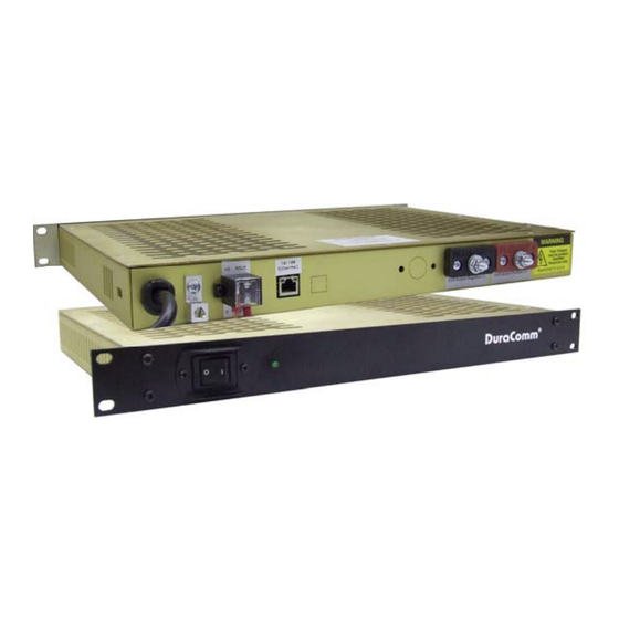
Internet Ready High Efficiency 1U AC to DC Power Supply
(These instructions are intended for use by a technician familiar with electronic products)
Input Voltage 90 to 264 VAC
13.8 VDC Output @ 54 Amps Max
Remote Monitoring of Power supply Voltage and
Current, and an External Alarm.
Remote control of power supply ON/OFF and External
Alarm output ON/OFF via Web Interface
Short Circuit / Overload / Over Voltage / Over
Temperature Protection
Output Power Led
3 year warranty
SPECIFICATIONS
Output Voltage ....................................................................................................................................................................... 13.8 VDC
Output Voltage Tolerance .......................................................................................................................................................... +/- 1 %
Output Amperage ........................................................................................................................................................... 54 Amps max.
Maximum Power, continuous ................................................................................................................................................ 750 Watts
Maximum Ripple and Noise ........................................................................................................................................ 150 mV p-p max
Input Voltage, Switch Selectable ................................................................................................................................. 110-or 220 VAC
Input Frequency Range ........................................................................................................................................................... 47-63 Hz
Maximum AC Current ............................................................................................................. 8.2 Amps/115 VAC; 3.9 Amps/230 VAC
Typical Efficiency .......................................................................................................................................................................... 89 %
Max Inrush Current, single cycle ........................................................................................... 25 Amps / 115 VAC, 40 Amps / 230VAC
Short Circuit Protection ................................................................................................................................. Constant Current Limiting
Overload Protection (operates) ................................................................................................................................. typical 105-125 %
Line Regulation ....................................................................................................................................................................... +/- 0.5 %
Load Regulation ...................................................................................................................................................................... +/- 0.5 %
Fan Control ................................................................................................................................... Heat sink temp >140 F (60 C) = ON
Over Temperature ........................................................................................................................ >195 F (90 C) auto output shutdown
Rise Time following ON ............................................................................................................................................................... 50 mS
Hold Time following OFF ............................................................................................................................................................. 10 mS
Working Temperature Range ............................................................................................................. -22 F to +158 F (-30 C to +70 C)
Storage Temperature ......................................................................................................................... -40 F to +185 F (-40 C to +85 C)
Withstand Voltage .................. 3 KVAC @ 10 ma (I/P-O/P)/1 min, 2 KVAC @ 10 ma (I/P-FG)/1 min, 500 V @ 10 ma (O/P-FG)/1 min
Dimensions ...................................................................................................................................................... 1.75" H x 19" W x 13" D
Weight ......................................................................................................................................................................................... 8.0 lbs
HE1U‐5012‐MU
Owners Guide
1
of 20
December 18, 2015
Advertisement
Table of Contents

Related Manuals for DuraComm HE1U-5012-MU


Summary of Contents for DuraComm HE1U-5012-MU
- Page 1 HE1U‐5012‐MU Internet Ready High Efficiency 1U AC to DC Power Supply Owners Guide (These instructions are intended for use by a technician familiar with electronic products) Input Voltage 90 to 264 VAC 13.8 VDC Output @ 54 Amps Max Remote Monitoring of Power supply Voltage and Current, and an External Alarm.
-
Page 2: Installer Notes
RMCU SPECIFICATIONS Network Connector ......................RJ-45 (10/100 Ethernet) with activity LEDs Backup Battery ..................................CR2032 Memory Card ................................. 4GB Micro SD Voltage Measurement Range ..........................0 VDC to 100 VDC Current Measurement Range ..........................0 Amps to 100 Amps Digital Alarm input ............................Normally Closed Contacts Alarm Output .............. -
Page 3: Installation Block Diagram
The Alarm Output is an open drain MOSFET referenced to G. The Alarm Output (AOut) Can Sink a maximum of 500 mA at a maximum voltage of +60 VDC for the revision 2 monitoring hardware included with the HE1U-5012-MU. The Alarm Input (Ain) is referenced to G, and is a LED in series with a 220 Ohm resistor internally, and can withstand 50 mA max. -
Page 4: Using Dhcp
CONNECTING TO THE HE1U-5012-MU VIA THE INTERNET Prerequisites System administrators must decide whether the HE1U‐5012‐MU will operate on the network with DHCP or a fixed IP address. The factory‐set HE1U‐5012‐MU will have these static addresses: IP address: 192.168.100.220, gateway address: 192.168.100.1, netmask: 255.255.255.0, and DNS address: 192.168.100.1. If you configure it to use DHCP, the HE1U‐5012‐MU will request an available IP address on your network. You will need to determine what address it has been given. If DHCP is not used, system administrators must also choose an unused IP address, and other network settings to use in the Network Setup screen. System administrators will also need to choose an email service and address to use for notifications, if needed. These will be used in the Email Setup Screen. DETERMINING THE IP ADDRESS OF THE HE1U-5012-MU Power up the HE1U‐5012‐MU then connect the HE1U‐5012‐MU to the network with an Ethernet cable. Using DHCP You will need to get the IP address in one of two ways. You can get the IP address from the DHCP server’s client list, or you can use a PC on the same network to scan for the new IP address by using a software tool such as Angry IP Scanner. In Angry IP Scanner, you should add the MAC address “Fetcher” under “Tools > Fetchers”. The DuraComm MAC 70‐B3‐D5‐6B‐3. addresses all start with a base address of Write down the IP address of the HE1U‐5012‐MU, then proceed to the section in this manual named “Open a Web Connection to the HE1U‐5012‐MU”. Using Static HE1U-5012-MU IP and Network Configuration If your network is not set up for DHCP, you will need to manually configure the settings to match the network it will be ... - Page 5 Open a Web Connection to the HE1U-5012-MU 1. Connect the RJ‐45 connector on the back of the HE1U‐5012‐MU to your network 2. Use your favorite device and browser (Chrome, Firefox, internet Explorer, etc.), and enter the IP address of the power supply on your network into the URL box on the browser (see the screenshot below). If you are unable to connect to the device with the browser, you will need to use a terminal with a USB connection to access the device and configure the IP address. If the HE1U‐5012‐MU responds with the “Status” screen, then skip to the User Login Section. of 20 December 18, 2015...
-
Page 6: User Login
REMOTE MONITORING AND CONTROL (HE1U-5012-MU) SETUP All setup requires an administrative user to log into the HE1U-5012-MU in your power supply. Click the ‘Login’ button in the top menu. User Login Enter the user name and password. Factory default username and password are as follows: Admin Users have full control of the device. -
Page 7: Network Setup
NETWORK SETUP of 20 December 18, 2015... - Page 8 Network Setup A network administrator for your company must choose the settings for this page. The default HTTP port is 80. If a different HTTP port is used, it will need to be added to the URL to access the RLP‐812‐MU. For example: if the port is changed to 8080 then the address would be changed to http://192.168.0.253:8080 NOTE: You must reboot the device for changes in these settings to take effect. SNMP TRAPS SETUP This section is simplified, and meant for network administrators who already understand SNMP traps and how to configure capable equipment into their system. For those who want to understand the benefits of using SNMP traps, you can search for training material online under “SNMP Traps”, “MIB Browsers”, and “SNMP Monitoring”. The MIB file for the HE1U‐5012‐MU can be downloaded from the HE1U‐5012‐MU after you connect to it with your browser. Go to the Device Setup page and log in to the HE1U‐5012‐MU. Halfway down the page there is a link to the MIB file. Right click on the link and click “Save Link As” to download the file. After download, import the MIB file into your MIB browser or Monitoring software to configure it for use with the HE1U‐ 5012‐MU. When the MIB file has been loaded, complete the “SNMP Setup” section on the “Network Setup” page of the HE1U‐ 5012‐MU to configure it for use with your monitoring solution. The HE1U‐5012‐MU will send traps for all configured alarm conditions including bootup, temperature, analog alarms, and digital alarms. Digital Outputs can also be controlled by SNMP on the HE1U‐5012‐MU. of 20 December 18, 2015...
-
Page 9: E-Mail Setup
EMAIL SETUP Email Setup Enter the required email setup parameters given to you by your System Administrator. You can also send a test email from this screen. of 20 December 18, 2015... -
Page 10: Device Setup
DEVICE SETUP of 20 December 18, 2015... -
Page 11: Device Info
Device Info A custom site name can be entered here, and the model number, serial number, software version, and hardware version are shown here. Logging The HE1U‐5012‐MU will log all measurements and alarms to an SD card that is plugged into the HE1U‐5012‐MU board. Users can set the rate here, as well as clear the card, or append new measurements. The CSV log file can be downloaded here, as well as the Status page. If the SD card fills up, the oldest sample is discarded when a new one is stored. The HE1U‐5012‐MU custom device name is stored with the logged data, so that the source of the card can be identified after it removed from the HE1U‐5012‐MU. SNMP MIB File Download The SNMP MIB File can be downloaded from this page. Date and Time Settings Configuration for all date and time settings. Date and time is battery backed up on the card, and the values are saved in the logged samples. The real‐time‐clock can synchronize it’s time to the network through an NTP server, or it can be set manually if a network is not available. time.nist.gov or pool.ntp.org, The NIST NTP servers can be used by entering or another NTP server address into NTP Server box. Miscellaneous Settings With Firmware 2.0, you can set the number of significant digits for the Analog Voltage readouts on the Status page, as well as set the temperature units. of 20 December 18, 2015... -
Page 12: Sensor Setup
SENSOR SETUP of 20 December 18, 2015... - Page 13 Sensor Setup Notes The admin user can set custom names for each input or output. Factory set names will be supplied, but they can be re‐ written to be more descriptive, or to manage larger systems. Alarm colors can be set here to represent the proper logical state for your system. Digital inputs can also be set here to send notification emails to the email address configured in the Email Setup screen. If any of the name fields on the left are left blank, the channel will be hidden on the status screen. Inputs and outputs of the HE1U‐5012‐MU board are wired as shown on the Sensor Setup screen. Analog alarms are set up in the “Alarm Setup” screen. See the “Alarm Setup” section for more information. In the HE1U‐5012‐MU the Digital Output 1 is an alarm output, and Digital Output 2 controls the ON/OFF state of the power supply. The user must be logged in as the admin or control user to control the digital outputs. The digital outputs can be controlled by the buttons on the status page, mobile page, or via SNMP on the HE1U‐5012‐MU. Optionally, they can be automatically controlled by connecting them to an alarm on the “Alarms” screen. In Revision 2.2 Firmware (see Device Setup screen) the user can enter text to change the user meaning of the digital output states, and there are 3 color options for the buttons. “Active means that the digital output MOSFET is conducting. Digital Output 1 can also be configured to output a 500uS pulse. of 20 December 18, 2015...
-
Page 14: Alarm Setup
ALARM SETUP of 20 December 18, 2015... - Page 15 Alarm Setup To set up analog alarms, first you must select the alarm channel to set. This is accomplished by selecting the custom name of the channel in the dropdown box next to the “Analogs” label. For example, we are looking at the settings for the “Module #1 Amps” channel in the screen above. Firmware 2.0 includes additional settings for alarms. This screen is where thresholds are set to define alarm conditions for the analog channels. You can choose to set an email notification when the alarm conditions are met. Factory Default Alarm Settings MEASUREMENT UNITS OVER ALARM OVER ALARM RECOVER UNDER ALARM UNDER ALARM RECOVER AC Line Voltage Volts 140 135 100 107 Temperature Fahrenheit 150 145 40 45 Power Supply Amps Amps ‐1000 0 1000 ...
-
Page 16: User Setup
USER SETUP User Setup Password changes and HE1U‐5012‐MU hard resets are perform by using this page. Care should be taken when changing any of these settings. NOTE: To hard reset your device back to factory settings, press the red button on the HE1U‐5012‐MU PCB and hold it for more than 30 seconds. You will need to re‐connect to the HE1U‐5012‐MU through your web browser by entering the factory supplied IP address and HTTP port (see Network Setup). of 20 December 18, 2015... -
Page 17: Status Screen
REMOTE MONITORING AND CONTROL STATUS PAGE Status screen This screen shows the status of all analog and digital inputs. A user can also download the Log file from this page. AC Voltage is approximate. of 20 December 18, 2015... - Page 18 Mobile Status Screen A simplified version of the status page is available for mobile devices. Just use the same IP address and add ‘/m’. for example 192.168.100.220/m HE1U-5012-MU MAINTENANCE Battery The battery on the HE1U‐5012‐MU is used to back up the real time clock for logging purposes. Logged in users can see the current system time on the Device Setup page under Date and Time settings. of 20 December 18, 2015...
- Page 19 CONDUCTOR PRETREATMENT All kinds of copper conductors can be clamped without treatment. DO NOT solder tin stranded conductors. The solder yields and fractures under high pressure. The result is increased contact resistance and excessive temperature rise. Additionally, corrosion has been observed due to the fluxes. Notch fractures at the transition from the rigid tinned part to the flexible conductors are also possible.
-
Page 20: Limited Warranty
DuraComm reserves the right to change, alter, or improve the specifications of its products at any time, and by so doing, incurs no obligation to install or retrofit any such changes or improvements in or on products manufactured prior to inclusion of such changes.
Need help?
Do you have a question about the HE1U-5012-MU and is the answer not in the manual?
Questions and answers