Table of Contents
Advertisement
Quick Links
Advertisement
Table of Contents

Subscribe to Our Youtube Channel
Related Manuals for Comtrend Corporation CT-510


Summary of Contents for Comtrend Corporation CT-510
-
Page 1: Adsl Router
CT-510 ADSL Router User Manual Version A3.0, June 3, 2003 261028-002... - Page 2 Preface This manual is designed to provide information to network administrators. It covers the installation, operation and applications of the CT-510 ADSL router. The reader is presumed to have a basic understanding of telecommunications. For product updates, new product releases, manual revisions, software...
-
Page 3: Table Of Contents
2.1.1 Rear Panel Connectors ............10 Preparing Installation ............11 Installation ............... 13 CHAPTER 3 MANAGEMENT ............14 Getting Started ..............14 How to access CT-510 ............15 3.2.1 Console................15 3.2.2 Telnet................16 3.2.3 Web ................18 General Configuration Steps in Console/Telnet ....... 19 3.3.1... - Page 4 4.1.5 Console Session Timeout ............ 24 4.1.6 Login Name & Passwords............ 24 Quick Configuration ............25 4.2.1 LAN Interface ..............25 4.2.2 ATM Interface ..............26 4.2.3 ATM VC Parameters ............27 4.2.4 ISP.................. 28 4.2.5 ADSL Retrain ..............29 Basic Configuration ............
- Page 5 Enable PAT/NAT..............36 PAT Virtual Server ............. 37 7.3.1 Add Virtual Server Entry............. 37 7.3.2 Delete Virtual Server............38 7.3.3 List Virtual Server Entry ............. 38 Configure NAT/PAT IP Pools..........38 7.4.1 Private IP Address ............. 39 7.4.2 Global IP Address .............. 39 7.4.3 Private/Global IP Pool Mapping ..........
- Page 6 11.1 Load Factory Default Values ..........45 11.2 Write System Configurations ..........45 11.3 Reboot System..............46 11.4 Software Upgrade.............. 46 11.5 Configuration Backup and Restoration ........47 11.5.1 Configuration Backup ............47 11.5.2 Configuration Restoration ........... 47 11.6 ADI Firmware Upgrade ............48 11.7 Homepage Upgrade ............
-
Page 7: Chapter 1 Introduction
Chapter 12: operation & configuration via Web. 1.1 Overview The CT-510 ADSL router uses the ADI chipset to satisfy the needs of multiple users for small office/home office and remote office/branch office applications. The router has an integrated 4-port 10-BaseT, half-duplex Ethernet hub. It can access the Internet, Corporate LAN or Video on demand over one ordinary telephone line at speeds up to 11 Mbps. -
Page 8: Features
Features Compact and high performance standalone unit Bridge/Routing function Fast ADSL up to 11 Mbps ANSI T1.413, G.DMT, G.lite Auto-negotiation rate adaptation AAL5 for ATM over ADSL UBR / CBR /VBR ATM services VC-based and LLC multiplexing Up to 16 VCs 4 port 10BaseT Ethernet hub, half-duplex One console port for local management Embedded SNMP agent and ADSL Forum TR-006 ADSL Line MIB... -
Page 9: 1.3 Application
1.3 Application The following diagrams a possible application of CT-510. It can be used for G.lite and G.DMT applications. PSTN Micro filter ADSL (G.lite) ANSI T1.413 CT-510 ADSL POTS splitter shelf POTS splitter CT-510 Figure 1-1 Application of CT-510... -
Page 10: Chapter 2 Hardware Installation
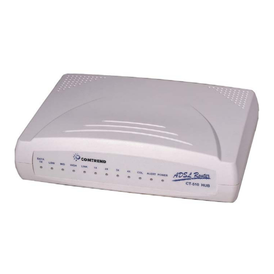
There are 12 LED indicators on the front panel (Fig.2-1). The description of each LED is given in the table below. DATA HIGH LINK ALERT POWER CT-510 Color Mode Function 12VAC power input is supplied to this unit POWER Green Power is not connected... -
Page 11: 2.1.1 Rear Panel Connectors
Note 2. The HIGH, MID, and LOW LEDs are OFF when no downstream data is received. 2.1.1 Rear Panel Connectors There are seven connectors on the rear panel. To make a connection using these connectors, please refer to Section 2.3. Power Console ADSL Figure 2–1 CT-510 Rear Panel Connectors... -
Page 12: Preparing Installation
• RJ45 10BaseT Ethernet connector cable(s) to connect to 1x – 4x ports– An RJ45 LAN connection cable is needed to connect the CT-510 to the Local Area Network (LAN). Maximum four Ethernet cables are required for 1x ~ 4x LAN port connection to the Ethernet devices. - Page 13 • An RJ11 connection cable to connect to ADSL port– An RJ11 connector cable is used to connect the CT-510 to the telephone line from the telephone company. The following lists the pin assignments of the RJ11 connector. Definition Definition...
-
Page 14: Installation
Installation The backplane connectors of the CT-510 can be configured to the following connections. Figure 2-3 illustrates possible connections of these connectors. Console Power RJ11 RJ45 12VAC POTS Power Splitter Adapter RJ45 RS-232 RJ45 RJ45 Phone Line Ethernet Equipment 110 / 220 VAC... -
Page 15: Chapter 3 Management
Chapter 3 Management 3.1 Getting Started This section is to help the users who will access the device for configuration, operation, or monitor purpose. It collects some important messages and suggestions that users may ignore during their operation. You may see the same messages or expressions throughout the content, just to keep from incorrect operations. -
Page 16: How To Access Ct-510
3.2 How to access CT-510 Three methods are available to access the device. You can choose from console, Telnet, or Web. Any of the methods can be used to access, configure, operate or monitor the device. Below shows how to get accessed to the device. -
Page 17: 3.2.2 Telnet
210.65.231.206. Step 2 You will be prompted to enter your user name and password. Comtrend Corporation CT-510 ADSL Router Login:root Password:**** To have full access privileges as an ADMINISTRATOR, type root in the Login field. If the default password was changed, type the... - Page 18 3.1.1, Steps 9-13). If the default password was not changed, type root. To have read-only access as a common USER, type user in the Login field. If the default password was changed, type the password that was set in the console session (refer to Section 3.1.1, Steps 9-13).
-
Page 19: 3.2.3 Web
Step 3 The main page displays. Step 4 For more information on configuring the CT-510 through the Web, refer to Chapter 12. Note: When a user has entered the system via the Web, no other users can access the device via the Web at the same time. Other users can access the device... -
Page 20: General Configuration Steps In Console/Telnet
You can easily find the directory of the menu, branch menu, or leaf menu via the path. For example, if you want to configure the LAN interface of the CT-510, please complete the following procedures. - Page 21 Step 4 Enter a parameter in each field. For fields that include the word, TAB, e.g., Network Type (TAB), press the TAB key to select a parameter from the pre-defined values. Then save the settings in RAM by holding down the Ctrl-S keys. Step 5 Return to the main menu and enter the WRITE menu to save the configurations from RAM to flash memory.
-
Page 22: Menu Layout
3.3.2 Menu Layout The operating menu of the CT-510 follows a tree-structured design and is divided into three categories: main menu, branch menu and leaf menu. You can select each menu item by using the up, down, left and right arrow keys on the main and branch menus. -
Page 23: Keyboard Operations
3.3.3 Keyboard Operations 1. UP Up arrow key. The cursor moves up one field on the configuration menu. 2. Down Down arrow key. The cursor moves down one field on the configuration menu. 3. Left-Prev Menu Left arrow key. It returns to the previous menu. 4. -
Page 24: Chapter 4 Initial Configuration (Console/Telnet)
Enter the MAIN/CONF/SYSTEM menu. In the Operation Mode field, select bridge or router for the CT-510. If bridge mode is selected, the IP address of the LAN interface is considered the bridge IP, and the IP addresses of the ATM interfaces are not applicable. -
Page 25: Adsl Physical Mode
4.1.3 ADSL Physical Mode Enter the MAIN/CONF/SYSTEM menu. In the ADSL Physical Mode field, press the TAB key to select a physical mode. The following modes are supported: ANSI (full rate), ANSI (Splitterless), G992_1(G.DMT), G992_2(G.lite), Auto Mode, and Fast ADSL(Auto). If Auto Mode is selected, the device can auto-detect the following modes from the CO side: ANSI (full rate), ANSI (Splitterless), G992_1(G.DMT), G992_2(G.lite). -
Page 26: Quick Configuration
Quick Configuration This section describes how to configure the basic environment (the interface and ISP) for the CT-510 via the console or Telnet. The CT-510 supports two interfaces: Ethernet and ADSL link interface. It can connect to a local area network via the Ethernet interface and to a wide area network via the ADSL link interface. -
Page 27: Atm Interface
The CT-510 supports PPP, PPPOE, Routed RFC1483 and Bridged RFC1483. The CT-510 and the remote ISP should use the same network service to establish the session. For PPP and PPPOE network services, the device supports two authentication protocols: PAP and CHAP. -
Page 28: Atm Vc Parameters
You can enter the MAIN/MON/ATM menu to see what IP address and subnet the device is assigned. 4.2.3 ATM VC Parameters The CT-510 supports 16 virtual channels. Step 1 Enter the MAIN/QC/VC menu. Step 2 Enter a VC leaf menu, VC1 to VC16, e.g., MAIN/QC/VC/VC1. -
Page 29: Isp
Hold down the Ctrl-S keys to save the parameters. 4.2.4 ISP should be configured when PPP or PPPOE is selected. The CT-510 can be connected to eight ISPs respectively with different VPI/VCI values. procedure below shows how to configure the necessary parameters to connect to an ISP. -
Page 30: Adsl Retrain
4.2.5 ADSL Retrain The CT-510 provides Hot-Key for ADSL retrain. Step 1 Enter the MAIN/QC/ADSL RETRAIN menu. Step 2 Enter a parameter in each field. Hot Key: Enable/Disable Retrain: Enable/Disable Step 3 Hold down the Ctrl-S keys to save the parameters. -
Page 31: Adsl Characteristics Parameters
ADSL Characteristics Parameters In the MAIN/CONF/ADSL menu, the administrator can set up the system chipset’s characteristics, such downstream framing, scramble, echo cancellation, and bit swapping functions. Another menu located at the directory of MAIN/MON/STATUS also displays these settings for monitoring purposes only. -
Page 32: Chapter 5 Bridging
Chapter 5 Bridging Overview Chapter 5 and Chapter 6 describe how to configure the CT-510 in order to forward packets to LAN and ATM WAN interfaces. The CT-510 supports both bridging and routing modes. A bridge forwards packets on the basis of a physical level or Medium Access Control address (MAC). -
Page 33: Delete A Static Mac Address
MAIN/CONF/BRIDGING/STATIC/LIST menu. Spanning Tree Protocol The default setting of the Spanning Tree Protocol (STP) function of the CT-510 is disabled. To enable it, follow these steps. Step 1 Enter the MAIN/CONF/BRIDGING/STP/BRIDGE menu. Spanning Tree: Enabled, Disabled (factory default: Disabled) Priority (0-65535) Step 2 Choose Enabled in the Spanning Tree field. -
Page 34: Chapter 6 Ip Routing
Hold down the Ctrl-S keys to save the parameters. The RIP function is now enabled. The default RIP parameter for each interface is RIPv1. In this default mode, the CT-510 can operate normally without other adjustments. If you want to configure advanced RIP functions, perform the... -
Page 35: Static Route Configuration
List Static Routes To view the static routes, enter the MAIN/CONF/ROUTING/STATIC/LIST menu. Routing Table In order to validate the above RIP configuration for each interface, the CT-510 provides one utility function to access the routing table, located on the MAIN/UTIL/ROUTING menu. -
Page 36: Ping Test Utility
Ping Test Utility The ping test is used to verify the status of the network connection after the RIP or static route function is enabled. It sends a request message to the host and waits for a return message. This diagnostic function can verify if the remote host is reachable for Telnet or FTP purposes. -
Page 37: Chapter 7 Network & Port Address Translation
Internet, the public addresses are becoming more scarce. One solution to this problem is to use private addresses in the small LANs and to use Address Translation when accessing the CT-510 on a public network. Both Port Address Translation (PAT) and Network Address Translation (NAT) are supported by the CT-510. -
Page 38: Pat Virtual Server
If you want to set up Internet servers in the virtual LAN when PAT is enabled in Section 7.2, you should register the servers with the CT-510 first to allow Internet users to access the service via the ATM interface of CT-510. -
Page 39: Delete Virtual Server
Assign the private IP addresses. Refer to Section 7.4.1. Step 2 Assign the global IP addresses. The CT-510 allows up to five sets of continuous global IP addresses. The workstations in the private IP pools will be translated to one of the global IP addresses that is set in Section 7.4.2. -
Page 40: Private Ip Address
7.4.1 Private IP Address Step 1 Enter the MAIN/CONF/NAT/PRIVATE menu. Step 2 Enter the following parameters. A maximum of five IP address pools can be configured. Pool Number: Pool 1 to Pool 5 Start IP Address: Enter the first IP address of the address pool. End IP Address: Enter the last IP address of the address pool. -
Page 41: Delete A Nat/Pat Pool Translation
Delete a NAT/PAT Pool Translation Step 1 Enter the MAIN/CONF/NAT/TRANSLATION/DELETE menu. Step 2 Enter a parameter in each field. Private IP Pool: press the TAB key to select a private pool number. Global IP Pool: press the TAB key to select a global pool number. -
Page 42: Chapter 8 Dns Proxy
A Domain Name Server (DNS) provides an IP address to a host computer for an applied Domain Name. The CT-510 supports the DNS proxy feature, which receives and attempts to find an entry in its local tables, and when one is not found, forwards the request to a remote server. -
Page 43: Chapter 9 Dhcp
IP address and parameters. When a workstation is configured for automatic IP address assignments, it broadcasts a request to the LAN. The CT-510 acts as the DHCP server and responds with: An IP address and subnet mask for the workstation... -
Page 44: Chapter 10 Snmp
Chapter 10 SNMP The CT-510 supports SNMP (Simple Network Management Protocol) and ILMI (Integrated Local Management Interface). SNMP: MIBs of MIB II and ADSL Forum TR006 are implemented. The default settings for read-only/read-write communities are public and private. ILMI: The Link Management MIB of the ILMI MIBs is implemented. The default setting of the ILMI is disabled with the value, 0/16, for VPI/VCI. -
Page 45: Delete A Trap Destination Entry
10.2.2 Delete a Trap Destination Entry Step 1 Enter the MAIN/CONF/SNMP/TRAP menu. Step 2 Enter a parameter in the following fields to delete a trap destination entry: Version: Select Version 1 or Version 2. Destination IP: Enter the destination IP address. Community: Enter a parameter for the community. -
Page 46: Chapter 11 Maintenance
Chapter 11 Maintenance 11.1 Load Factory Default Values Step 1 Enter the MAIN/DEFAULT menu. Step 2 On the menu, the following message displays: “This will set system parameters to factory default! (Y/N).” Step 3 Press the Y key. The system restores the default configurations. Step 4 After the default values are restored, the following message displays: “Set system parameters to factory default! Press any key to... -
Page 47: Reboot System
11.3 Reboot System After the parameters are written in the flash memory, you must reboot the system to make the new parameters effective. Step 1 Enter the MAIN/REBOOT menu. Step 2 The prompt “This will reboot the system? (Y/N)” displays. Step 3 Press the Y key to reboot the system. -
Page 48: Configuration Backup And Restoration
11.5 Configuration Backup and Restoration The device utilizes the TFTP protocol to back up and restore the current configuration parameters. administrator save configuration parameters as a file and retrieve it later. To perform the functions, you can set up a TFTP server, which can be LAN-connected or WAN-connected to the device. Then refer to the following sub-sections to configure the required parameters. -
Page 49: Adi Firmware Upgrade
11.6 ADI Firmware Upgrade The device utilizes the TFTP protocol to upgrade the ADI firmware of the device’s chipset. Follow the steps below to upgrade the ADI firmware. Step 1 Enter the MAIN/UTIL/TFTP menu. Step 2 Enter a parameter in the following fields: TFTP Server IP Address: Enter the TFTP Server IP address. -
Page 50: Performance Monitoring
11.8 Performance Monitoring Enter the MAIN/MON menu. You can monitor the following ATM statuses: ADSL Status Monitor ATM Interface Monitor ADSL Performance Statistics Interface Performance Statistics 11.8.1 ADSL Status Monitor You can monitor the ADSL status from the MAIN/MON /STATUS menu. Hardware status Software status Initialization status... -
Page 51: Atm Interface Monitor
11.8.2 ATM Interface Monitor You can view the ATM interface statuses from the MAIN/MON/ATM menu. In PPP or PPPoE mode, the router can auto-detect the IP address of the DNS server via the PPP negotiation process. This menu will ignore the IP address that is set up on the MAIN/CONF/DNS menu, and it displays the one that is dynamically detected. -
Page 52: Interface Performance Monitor
11.8.4 Interface Performance Monitor You can monitor the interface performance statistics of LAN and ATM1 to ATM16 on the MAIN/MON/INTRPREF menu. You can reset the items marked since reset by holding down the Ctrl-T keys. Interface: LAN or ATM interfaces Transmitted packets (since reset): the transmitted packets since last reset Received packets (since reset): the received packets since last... -
Page 53: Chapter 12 Web Configuration
Chapter 12 Web Configuration This chapter describes how to manage the device via the Web browser from the remote end. The Web page is best read with a display resolution of 1024 x 768 or 800 x 600. Web management is enabled by factory default. If you don’t need this function, you can disable it using either of the following methods: Enter the MAIN/CONF/HTTPD menu from the console or through Telnet. - Page 54 Figure 12-1 Web Main Menu Step 5 On each Web page, there are three basic areas: The first area is the main menu on the top. It includes the following buttons: 1. Home: Web main menu 2. Setup: Quick Setup 3.
-
Page 55: Operation
12.2 Operation The Web page follows a tree-structured design. The operational methods are basically the same as the console and Telnet modes. Getting familiar with the console and Telnet is helpful and makes it easier to learn to configure through the Web browser. -
Page 56: Quick Setup
12.2.1 Quick Setup The Quick Setup Wizard includes five steps. The device can function normally after these five steps are completed. The Setup button links to a quick configuration page for the administrator to easily customize the device. It has the following functions: LAN Parameters ATM Interface Parameters... -
Page 57: Basic Configuration
12.2.2 Basic Configuration At this stage, the administrator can perform the following functions: Load Factory Default System Parameters (host name, domain name, operation mode, ADSL physical mode, user password) ISP Parameters ATM VC Parameters ATM Interface Parameters DHCP Parameters NAT Parameters Review Parameters Save and Restart Step 1... - Page 58 Static Route Parameters RIP Parameters Transparent Bridging Parameters SNMP Parameters TFTP Parameters HTTPD: to enable or disable the Web browser Save and Restart Step 1 Click the Advance button to access the Advance Configuration page. Figure 12-4 Advance Configuration Step 2 Follow the online explanations to configure each function.
-
Page 59: Utilities
12.2.4 Utilities Click Utility to access the Utilities page. The following briefly describes the functions on the Utilities page: Ping Test: to test specific network connection. Routing Table Utility: to see the routes of the system. Forwarding Table Utility: to see the forwarding table of the system. TFTP Application 1. -
Page 60: Appendix
Appendix Index of Console/Telnet Default LEVEL1 LEVEL2 LEVEL3 LEVEL4 LEVEL5 LEVEL6 Value NETWORK GLOBAL TYPE 210.65.23 IP ADDRESS 1.206 255.255.2 SUBNET MASK 55.0 ATM1~ATM1 INTERFACE ENABLED PROTOCOL ETHERNET IPCP STATIC ISP1 NETWORK GLOBAL TYPE ATM VC IP ADDRESS SUBNET MASK VC1~VC16 VPI/VCI 0/50... - Page 61 ADMINISTRATO R PASSWORD RETYPE PASSWORD USER PASSWORD RETYPE PASSWORD INTERFAC NETWORK GLOBAL TYPE 215.65.23 IP ADDRESS 1.206 255.255.2 SUBNET MASK 55.0 ATM1~ATM16 INTERFACE PROTOCOL ETHERNET IPCP STATIC ISP? NETWORK GLOBAL TYPE ATM VC 210.65.23 IP ADDRESS 1.207 255.255.2 SUBNET MASK 55.0 ISP1~8 ISP NAME...
- Page 62 GLOBAL IP ADDRESS PRIVATE IP DELETE ADDRESS GLOBAL IP ADDRESS PRIVATE IP LIST ADDRESS GLOBAL IP ADDRESS SERVER PROTOCOL INTERFACE SERVICE NAME SERVICE PORT NUMBER PRIVATE IP ADDRESS PRIVATE PORT NUMBER DELETE PROTOCOL INTERFACE SERVICE PORT NUMBER LIST PROTOCOL PRIVATE IP PRIVATE PORT SERVICE PORT INTERFACE...
- Page 63 TRAP VERSION VERSION 1 DESTINATION COMMUNITY DELETE VERSION VERSION 1 DESTINATION COMMUNITY LIST VERSION DESTINATION COMMUNITY SERVER IP TFTP ADDRESS FILE NAME VC1~VC16 VPI/VCI AAL5 ENCAPSULATI VC QOS PEAK CELL 960000 RATE (BPS) SUSTAINABLE CELL RATE (BPS) BURST TOLERANCE (MSEC) NETWORK/HO ROUTING STATIC ST ADDRESS...
- Page 64 VERSION AUTHENTICATION NONE POISON REVERSE ENABLED AUTHENTICATION CODE BRIDGIN STATIC MAC ADDRESS PORT MAP DELETE MAC ADDRESS LIST MAC ADDRESS OPERATION BRIDGE SPANNING TREE DISABLED PRIORITY 32768 PORT INTERFACE OPERATION ENABLED PRIORITY HTTPD WEB SERVER ENABLED DOWNSTREAM ADSL MODE 3 FRAMING SCRAMBLE ENABLED...
- Page 65 (SINCE RESET, CUURENT MIN/ 1DAY) LOS (SINCE RESET, CUURENT MIN/ 1DAY) (SINCE RESET, CUURENT MIN/ 1DAY) (SINCE RESET, CUURENT MIN/ 1DAY) INTRPREF INTERFACE TXPKTS RXPKTS EXERRORS TX RATE (BPS) RXRATE(BPS) STATUS TFTP UTIL TFTP SERVER ADDRESS FILE NAME TFTP DOWNLOA OPTION APPLICATIO FIRMWARE...
- Page 66 QUIT...
-
Page 67: Specifications
Specifications WAN interface (one ADSL port) Item Specifications ADSL standard ANSI T1.413 ISSUE 2, G.DMT, G.lite G.DMT data rate Downstream: 8 Mbps Upstream: 1 Mbps G.lite Downstream: 1.5 Mbps Upstream: 512 Kbps ATM attributes Item Specifications PPP over AAL5 RFC2346 Multi-protocol over AAL5 RFC-1483 IP over AAL5... - Page 68 Routing functions Item Specifications IP static route RIP and RIPv2 Network functions Item Specifications DNS, NAT/PAT, DHCP/BOOTP PAP, CHAP Power supply Item Specifications Power source 110 VAC or 220 VAC (50 or 60 Hz) Power consumption 6.0W Input voltage 12 to 14 VAC, minimum 600 mA Environmental conditions Item Specifications...
-
Page 69: Trouble Shooting
Edition 4 or below. Solution2: If you don’t want Solution 1, you can upgrade the firmware of CT-510 to Version 1.67 or above. For Version 1.67 and above, you can use other functional keys to replace the arrow keys. For example, the function of UP arrow key can be replaced by holding down CTRL-W.
Need help?
Do you have a question about the CT-510 and is the answer not in the manual?
Questions and answers