Table of Contents
Advertisement
Quick Links
Advertisement
Table of Contents

Related Manuals for SpectraDynamics HPDA-15RM-C

Summary of Contents for SpectraDynamics HPDA-15RM-C
- Page 1 PECTRA YNAMICS, ERFORMANCE ISTRIBUTION MPLIFIER HPDA-15RM-C PERATING ANUAL PECTRA YNAMICS, NC • 1849 Cherry St. Unit 2. • Louisville, CO 80027 Phone: (303) 665-1852 • Fax: (303) 604-6088 www.spectradynamics.com...
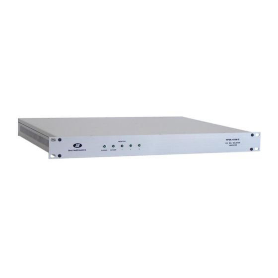
- Page 3 The HPDA-15RM-C is a high performance distribution and isolation amplifier. standard unit contains three HPDA-5 modules. Each module provides five unity gain outputs for every input signal. The HPDA-15RM-C may be modified upon request to contain only two HPDA-5 modules.
-
Page 4: Safety And Preparation For Use
Line Voltage This instrument may be setup to operate on 100-120 or 220-240 VAC and a line frequency of 50 to 60 Hz. The setup voltage for this HPDA-15RM-C is specified on page 4. Fuse A 0.50 Ampere 250V slow-blow fuse is used for 100-120 VAC operation. -
Page 5: The Front Panel
The DC POWER LED is on when DC power is applied to unit and the unit is operating properly. Monitor LED The MONITOR LED of each module will turn on if all the output signals to the corresponding module are greater than +7 dBm. Copyright © SpectraDynamics, Inc. 2010... -
Page 6: The Back Panel
Optional Battery Backup Connector for +24 VDC Backup power source. SMA INPUTS The standard HPDA-15RM-C contains three amplifier modules each having one input SMA connector. If you acquired a modified unit with only two HPDA modules the back panel will contain only two SMA input connectors. The signal to be distributed should be connected to the corresponding SMA jack labeled INPUT. -
Page 7: Battery Backup Module
Battery Backup Module Description The battery backup module allows the HPDA-15RM-C instrument to be powered by a +24 VDC power source in case of loss of the main AC power. The switch from AC to DC supply operation is affected by a Schottky diode network and charge storage capacitors to ensure glitch free operation. - Page 8 The +24 VDC connector is wired as follows: Pin 1 NC Pin 2 NC Pin 3 NC Pin 4 +24 VDC GND return Pin 5 +24 VDC power Pin 6 Chassis GND / Earth GND Copyright © SpectraDynamics, Inc. 2010...
-
Page 9: Operation
AC voltage. If you also apply the DC voltage the LED labeled DC POWER on the front panel should light up. Attach the signal to be distributed to one of the SMA input connectors on the back panel. Any HPDA-15RM-C output may be used to drive the input of another distribution module. -
Page 10: Specifications
10 Hz -165 -157 1 kHz -171 -169 10 kHz -172 -170 Temperature-delay 0 - 50 ºC ps/ºC Coefficient 25 - 35 ºC All tests done at 5 MHz and +13 dBm input unless otherwise specified. Copyright © SpectraDynamics, Inc. 2010... -
Page 11: Warranty
This warranty shall be in effect for one (1) year from the date a HPDA-15RM-C is sold by SDI. SDI makes no other warranty, express or implied, and makes no warranty of the fitness for any particular purpose. SDI’s obligation under this warranty shall not include any transportation charges or costs of installation or any liability for direct, indirect, or consequential damages or delay. - Page 12 HPDA-15RM-C:3I-15O/R02...
Need help?
Do you have a question about the HPDA-15RM-C and is the answer not in the manual?
Questions and answers