Advertisement
IMPORTANT! Read all instructions before installing and using. Installer: This manual must be delivered to the end user.
WARNING!
Failure to install or use this product according to manufacturer's recommendations may result in property damage, serious injury, and/
or death to those you are seeking to protect!
Do not install and/or operate this safety product unless you have read and understood the safety information
contained in this manual.
1.
Proper installation combined with operator training in the use, care, and maintenance of emergency warning devices are essential to
ensure the safety of emergency personnel and the public.
2.
Emergency warning devices often require high electrical voltages and/or currents. Exercise caution when working with live electrical
connections.
3.
This product must be properly grounded. Inadequate grounding and/or shorting of electrical connections can cause high current arcing,
which can cause personal injury and/or severe vehicle damage, including fire.
4.
Proper placement and installation is vital to the performance of this warning device. Install this product so that output performance of
the system is maximized and the controls are placed within convenient reach of the operator so that they can operate the system without
losing eye contact with the roadway.
5.
Do not install this product or route any wires in the deployment area of an air bag. Equipment mounted or located in an air bag
deployment area may reduce the effectiveness of the air bag or become a projectile that could cause serious personal injury or death.
Refer to the vehicle owner's manual for the air bag deployment area. It is the responsibility of the user/operator to determine a suitable
mounting location ensuring the safety of all passengers inside the vehicle particularly avoiding areas of potential head impact.
6.
It is the responsibility of the vehicle operator to ensure daily that all features of this product work correctly. In use, the vehicle operator
should ensure the projection of the warning signal is not blocked by vehicle components (i.e., open trunks or compartment doors),
people, vehicles or other obstructions.
7.
The use of this or any other warning device does not ensure all drivers can or will observe or react to an emergency warning signal.
Never take the right-of-way for granted. It is the vehicle operator's responsibility to be sure they can proceed safely before entering an
intersection, drive against traffic, respond at a high rate of speed, or walk on or around traffic lanes.
8.
This equipment is intended for use by authorized personnel only. The user is responsible for understanding and obeying all laws
regarding emergency warning devices. Therefore, the user should check all applicable city, state, and federal laws and regulations. The
manufacturer assumes no liability for any loss resulting from the use of this warning device.
Specifications
Length.................24", 30", 36", 42", 48", 54", 60", 72"
Width...................11"
Height..................2.5"
Voltage................12-24VDC
Current Draw.......Single Color LED Module = 0.55A Avg. @ 12.8VDC
Dual Color LED Module = 0.55A Avg. @ 12.8VDC
LED STT (pair) = 1.2A Avg.@ 12.8VDC
LED AL,TD,WL = 1.2A Avg. @ 12.8VDC
Flash Patterns.....70
Fuse Recommendation:
Calculate the total amp draw from all the LED Modules.
Multiply the total amp draw by 1.25. Round up to the
nearest fuse.
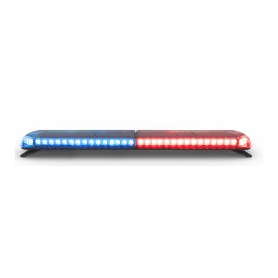
Installation and Operation Instructions
12+ Pro Vantage™ Series Lightbars
Page 1 of 14
Advertisement
Table of Contents

Related Manuals for Code 3 12+ Pro Vantage Series


Summary of Contents for Code 3 12+ Pro Vantage Series
- Page 1 Installation and Operation Instructions 12+ Pro Vantage™ Series Lightbars IMPORTANT! Read all instructions before installing and using. Installer: This manual must be delivered to the end user. WARNING! Failure to install or use this product according to manufacturer’s recommendations may result in property damage, serious injury, and/ or death to those you are seeking to protect! Do not install and/or operate this safety product unless you have read and understood the safety information contained in this manual.
-
Page 2: Installation And Mounting
Carefully remove the lightbar and place it on a flat surface. Examine the unit for transit damage and locate all parts. If damage is found or parts are missing, contact the transit company or Code 3. Do not use damaged or broken parts. Ensure the lightbar voltage is compatible with the planned installation. - Page 3 Strap Kit Mounting Loosen the 5/16” nuts to allow the mounting feet to slide along the IMPORTANT! Mounting brackets are specific to the vehicle model. base of the lightbar. Loosely attach the mounting strap to each foot Please make sure the brackets are suitable for the vehicle before using the supplied pan head phillips screws and lock washers.
-
Page 4: General Wiring Instructions
Wiring Instructions IMPORTANT! This unit is a safety device and it must be connected to its own separate, fused power point to assure its continued operation should any other electrical accessory fail. Notes: Larger wires and tight connections will provide longer service life for components. For high current wires it is highly recommended that terminal blocks or soldered connections be used with shrink tubing to protect the connections. - Page 5 COMBINED POWER/SIGNAL CABLE Combined Combined power/signal 12+ Pro Vantage™ Lightbar 12+ Pro Vantage™ Lightbar cable power/signal cable Combined Combined power/signal power/signal cable cable BLACK (GROUND) STTs OPTIONAL STTs OPTIONAL BROWN (PATTERN 1) BROWN (PATTERN 1) Optional Stop/Tail/Turn Optional Stop/Tail/Turn *Brown + Orange = Pattern 3 (STT) Cable (STT) Cable *Brown + Orange = Pattern 3...
- Page 6 SERIAL INTERFACE BOX (EZMATSIB) GRAY/BLACK - Ignition Wire GRAY/BLK - Ignition Wire Yellow - Left Alley YELLOW - Left Alley 12+ Pro Vantage™ Lightbar 12+ Pro Vantage™ Lightbar 4-Pin Connector 4-Pin Cable Purple - Right Alley PURPLE - Right Alley Gray - Worklights GRAY - Worklights ORG/BLK - Takedown Lights...
-
Page 7: Maintenance
Maintenance Occasional cleaning of the lenses will ensure optimum light output. Take care when cleaning lenses – although tough, polycarbonate scratches easily. Clean the lens and base with soap and water or a lens polish using a soft cloth. Do not use solvents as they may damage the polycarbonate. - Page 8 Advanced Controller (CZ1202) Provides convenient control of the lightbar’s built-in flash patterns and features soft touch buttons and LED function indicator lights. 12+ PRO ADVANCED CONTROLLER FUNCTIONS CODE3ESG.com P/N CZ1202 Toggle Press [Press for 2 Seconds] Select Flash Pattern 1 Takedown Cruise Progrom Flash...
- Page 9 “Safety Director On/Off” - Press once to turn the Safety Director on or off. “Safety Director Pattern Select” - Once the Saftey Director is activated, press this pattern select button to cycle to the next Safety Director flash pattern. There is a 5 second delay between the controller and the lightbar.
- Page 10 Advanced Control Pad Mounting: The advanced control pad is supplied with three mounting options: a BRACKET BRACKET bracket, VHB tape and hook and loop patch. The rear of the control pad is designed to allow for the cable exit to be routed five different ways to maximize installation locations.
- Page 11 Page 11 of 14...
-
Page 12: Replacement Parts/Accessories
Permanent mounting feet and hardware - Black ER0002 Permanent mounting feet and hardware - White ER0001 Headache rack mounting kit A1032RMK NOTE: For list of vehicle specific brackets, please contact a Code 3 representative or our latest catelog. Page 12 of 14... -
Page 13: Troubleshooting
Troubleshooting All lightbars are thoroughly tested prior to shipment. However, should NOTE: Operating the vehicle without the outer lens installed you encounter a problem during installation or during the life of the on the product may result in damage that will NOT be product, follow the guide below for troubleshooting and repair informa- covered under warranty. -
Page 14: Product Returns
*Code 3®, Inc. reserves the right to repair or replace at its discretion. Code 3®, Inc. assumes no responsibility or liability for expenses incurred for the removal and /or reinstallation of products requiring service and/or repair.;...
Need help?
Do you have a question about the 12+ Pro Vantage Series and is the answer not in the manual?
Questions and answers