
Related Manuals for GE Profile Performance ADVANTIUM SCA2000BAA


Summary of Contents for GE Profile Performance ADVANTIUM SCA2000BAA
- Page 1 GE Consumer Service Training TECHNICAL SERVICE GUIDE ADVANTIUM ™ SPEEDCOOKING MODEL SERIES: Profile Performance ™ SCA2000BAA SCA2000BBB SCA2000BCC SCA2000BWW SCA2001BSS PUB # 31-9038 10/99...
- Page 2 IMPORTANT SAFETY NOTICE The information in this service guide is intended for use by individuals possessing adequate backgrounds electrical, electronic mechanical experience. Any attempt to repair a major appliance may result in personal injury and property damage. The manufacturer or seller cannot be responsible for the interpretation of this information, nor can it assume any liability in connection with its use.
-
Page 3: Table Of Contents
TABLE OF CONTENTS Welcome to Advantium Installation Instructions Specifications Warranty Overview of Advantium Control Panel Features Cooking Guide How to Speedcook Operating Characteristics Index Mechanical Disassembly Index Troubleshooting Index Illustrated Parts Breakdown Six Sigma - What is it? Last Minute Additions - Addendum... -
Page 4: Welcome To Advantium
Included with the purchase of the Advantium™ The cooking guide is a 4 page, quick reference oven is an Advantium™ Owners Kit. The kit includes guide containing numerous helpful cooking tips. In addition it contains helpful use and care infor-... - Page 5 Other Features ..32–35 Owner's Manual Advantium Quick Start ..10 Auto night light ....32 Cooking controls ... . .13 Automatic fan .
-
Page 6: Installation Instructions
IMPORTANT – PLEASE READ CAREFULLY. INSTALLATION INSTRUCTIONS FOR PERSONAL SAFETY, THIS APPLIANCE MUST BE PROPERLY GROUNDED TO AVOID SEVERE OR FATAL SHOCK. REQUIREMENTS FOR INSTALLATION Fig. 1 NEMA 14-30R Wall Receptacle Important Safety Instructions Insure proper ground exists See electrical requirements for proper outlet before use. -
Page 7: Parts Included
OVERVIEW OF INSTALLATION PROCEDURE 6. Hook the slots at the back bottom edge of the oven onto the 2 lower tabs of the mounting This section gives a brief overview of what you plate and rotate it up. need to do to install this oven. Read these entire 7. - Page 8 HOOD EXHAUST DUCT Outside ventilation requires a HOOD EXHAUST DUCT. Read the following carefully. EXHAUST CONNECTION: The hood exhaust ″ has been designed to mate with a standard 3 x 10″ rectangular duct. If a round duct is required, a rectangular-to-round transition adaptor must be used.
- Page 9 REMOVE THE MOUNTING PLATE OVEN EXHAUST DUCT The mounting plate comes attached to the This oven is designed for adaptation to the back of the oven. following three types of ventilation. NOTE: This oven is shipped assembled for top 1. Stand the oven on its control panel side. Use a exhaust.
- Page 10 B. OUTSIDE BACK EXHAUST BEFORE: (Horizontal Duct) Fan Blade Openings Facing Up This oven is shipped assembled for top exhaust. Use the following steps to change it for outside Blower back exhaust. End B Unit 1. Remove and save the screws that hold the blower plate to the oven.
- Page 11 2. • Slide the blower plate back from under its 5. • Guide the wires into the duct as you place retaining flange and lift it off. the blower unit back into the opening. • Remove and save the screw that holds the •...
- Page 12 PREPARATION OF TOP CABINET OVEN EXHAUST DUCT (continued) You need to drill holes for the top support 4. • Guide the wires into the duct as you place screws and a hole large enough for the power the blower unit back into the opening. cord to fit through.
- Page 13 4. While holding the mounting plate with one 3. Draw a vertical line on the wall at the center of the 30″ wide space. hand, draw circles on the wall at holes A, B, C and D. Four holes must be used for Use the mounting plate as the template for mounting.
-
Page 14: Mount The Oven
ATTACH THE MOUNTING PLATE MOUNT THE OVEN TO THE WALL (continued) FOR EASIER INSTALLATION AND PERSONAL SAFETY, WE RECOMMEND THAT TWO PEOPLE INSTALL THIS OVEN. To prepare the rear wall cutout opening IMPORTANT: Do not grip or use handle during and exhaust adaptor/mounting plate for installation. -
Page 15: Installation Checklist
3. Attach the oven to the top cabinet. 4. Install the grease filters and remove the tape from the cooktop lamp covers on the bottom NOTE: of the oven. 1. You'll need to use a filler block if the cabinet 5. -
Page 16: Specifications
Advantium ™ Specifications: Specifications Nomenclature Six o'clock. What's for dinner? How Color Options about a delicious family meal, cooked in a fraction of the time needed in a Model SCA2000BAA Almond traditional oven? Model SCA2000BBB Black Model SCA2000BCC... -
Page 17: Warranty
Warranty: GE will replace: For the period of: • Full one-year warranty on Full one-year Entire oven parts and labor Any part of the oven which fails due to a defect in materials or From the date of the workmanship. During this full one-year warranty, GE will also original purchase •... -
Page 18: Overview Of Advantium
™ ADVANTIUM OVERVIEW Upper Halogen Lamp Assembly Black Metal Tray / Baking Sheet Two 1500 watt halogen lamps provide heat Used during speedcooking only. Put food from the top of the oven cavity. These directly on the black metal tray and place on... -
Page 19: Control Panel Features
SELECTOR DIAL The heart of the user controls. Just turn & tap to select cooking programs, adjust timer and power levels. SPEEDCOOK / REPEAT LAST START / PAUSE Allows user to select a pre-set Starts or pauses any speedcook program from a cooking function. -
Page 20: Cooking Guide
With these tips, you can easily take advantage of Table of Contents Advantium's flexibility in cooking to your taste, so food comes out just the way you want it. Quick Start ..... . . 18 Quick Start Cooking Controls . -
Page 21: Speedcook Preset Menu Guide
Speedcook Preset Menu Guide Advantium is already preset to cook more than 100 of America's favorite dishes. When speed cooking preset foods, refer to the following guide. This listing includes all of the preset food types, the brands that we tested and helpful cooking tips. -
Page 22: Food Placement
• Paper products and wraps should not be increase cooking time; smaller amounts will cook chicken pieces can also be cooked on the black used in the Advantium oven when cooking with in less time. metal tray. the speedcook feature. -
Page 23: Recipe Adapting
Recipe Adapting When adapting your favorite recipes for the Advantium oven, use the following charts as a guide. You may also find it helpful to refer to a similar recipe in the Advantium Cookbook to determine cook time and U/L/M settings. -
Page 24: How To Speedcook
Use ROUND METAL TRAY tor dial to begin cooking. the display with remaining Be sure the use the metal tray cooking time counting down. that came with the Advantium. YOUR FOOD IS READY OPTIMIZING COOK TIME CHECK for DONENESS 9:55... -
Page 25: Operating Characteristics Index
OPERATING CHARACTERISTICS Power Levels Voltage Compensation Upper Halogen Lamp Balance Thermal Compensation Thermal Protection Thermal Safety Damper Door Assembly Damper Door Sensing Switch Oven Cavity Lamp Thermal Fuse Air Flow Vent Motor Halogen Blowers - Upper/Lower Magnetron Blower 24-25 26-28 –... - Page 26 Example: upper element set at 80% (U=08), lower POWER LEVELS element set at 50% (L=05) and microwave set at Advantium uses power from high intensity halo- 30% (M=03) gen lamps, as well as microwave energy, to cook foods evenly and quickly (average of one-fourth...
- Page 27 When cooking several food items consecutively, 36.7 the temperature in the oven’s interior can become 26.3 very hot. The Advantium speedcooking program 16.7 (smart board) automatically compensates for the increased temperature by adjusting the cooking power levels of the upper and/or lower halogen -7.1...
- Page 28 upon the oven cavity temperature and the amount levels) depends upon the temperature of the oven of cooking time selected, the smart board will cavity at the start of the speedcook operation and adjust the power level of the upper and/or the the amount of time selected.
- Page 29 Start the speedcook operation and carefully no- THERMAL PROTECTION tice the cycling of the halogen lamps. At power If oven cavity temperatures reach somewhere in levels of 10, both the upper halogen pair, and the the range of 500 to 600 degrees, or if a speed- lower halogen lamp should be on 100% of the cooking selection is chosen which exceeds 12 time.
- Page 30 THERMAL SAFETY In the unlikely event that internal oven cavity tem- peratures exceed 600+ degrees F., speedcooking DAMPER DOOR SHOWN IN OPEN operation will be terminated. POSITION ALLOWING AIRFLOW INTO OVEN CAVITY The oven cavity thermistor is constantly sensing oven cavity temperatures and providing input to the smartboard.
- Page 31 the damper motor will continually cycle the The following damper door positions will occur damper door open and closed until one complete with various operations: switch cycle is detected. • When the oven is not in use (power ap- plied to the unit with time of day clock show- Damper Door Closed: ing), the damper door will always be in the The illustration below shows the position of the...
- Page 32 AIR FLOW into the room (depending on exhaust setup - see installation instructions in this manual for details There are 4 fan motors in the Advantium design on exhaust options). which provide airflow for proper cooling. During speedcooking (pre-selected recipe or manual speedcook) all four fan motors will run during the entire speedcook operation.
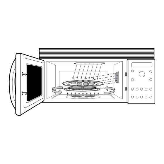
- Page 33 AIRFLOW - SPEEDCOOKING OPERATIONS HOT AIR EXHAUST AIR FROM COOKTOP, LOWER HALOGEN LAMPS, & OUTER CONTROL PANEL AREA HOT AIR FROM COOKTOP & LOWER HALOGEN LAMP HOT AIR FROM COOKTOP & LOWER HALOGEN LAMP AIR FROM AROUND THE OUTSIDE OF THE HOT EXHAUST AIR FROM CONTROL PANEL AREA UPPER HALOGEN PAIR...
- Page 34 MAGNETRON BLOWER ASSEMBLY During microwave operation room air is drawn in through the front grille (air inlet tunnel) and down into the magnetron blower area. The magne- tron fan blows the cool air through, and around the magnetron tube. The air then passes through the damper door assembly (damper door is open during microwave operation) into the oven cav- ity.
-
Page 35: Mechanical Disassembly Index
MECHANICAL DISASSEMBLY Front Serviceability Front Grille HV Capacitor & Diode Control Panel Assembly Control Panel Housing Low Voltage Transformer Relay Board Removal From Installation Outer Case Upper Halogen Blower/Lamp Assy. Thermistor - Oven Cavity Magnetron Blower Assembly Damper Door Assembly Thermal Fuse Lamp - Oven Cavity Magnetron Tube... - Page 36 Accessible after lowering the bottom SERVICEABILITY WITH OVEN INSTALLED base plate assembly The following components can be accessed from • Turntable drive motor & spindle the front of the oven with the unit installed: • Lower halogen lamp • Lower halogen thermal cut-out (TCO) Accessible after removing top front grille •...
- Page 37 FRONT GRILLE REMOVAL Grille removal is required in order to lower the CAPACITOR control panel, remove the door, or gain access to the line fuse, high voltage capacitor or high voltage diode. To remove the grille follow these DIODE steps: Remove the two screws located above the LINE FUSE grille which secure the grille to the upper-...
- Page 38 To remove the control panel assembly, discon- CONTROL PANEL REMOVAL & SERVICE nect all associated connector plugs on the smart The control panel is hinged at the bottom and board. Disengage the lower control panel hinge secured at the top with one screw. The right side tabs from the chassis and remove the complete of the control panel has alignment tabs which fit control panel assembly.
- Page 39 Notice in the illustration below, that the while the The relay board can also be replaced from the display looks like one complete assembly, it ac- front of the unit. Notice in the illustration below tually consists of two components (the VFD and that the relay board is mounted (screwed) to a the LED board).
- Page 40 SERVICEABILITY - OVEN REMOVED FROM After swinging the top of the oven forward (away from the cabinets) lift upward on the bottom of WALL MOUNTING PLATE the oven to release it from the mounting tabs of the wall plate. The following components require the oven to be removed from the wall mounting (removed from installation) plate prior to replacement: •...
- Page 41 To remove the outer case, first remove the power Lift off the outer case, feeding the power cord cord cover plate. through the opening in the top of the case. UPPER HALOGEN BLOWER/LAMP ASSEM- BLY REMOVAL Remove two screws from the bottom hood cover which secure the hood cover to the outer case.
- Page 42 in order to insure proper reinstallation. the blower/lamp assembly. They must be removed in order to remove the blower/ Remove the power cord ground wire from lamp assembly. the oven chassis. Note that this screw is a machine screw with fine threads. Be sure to mark this screw for proper rein- stallation.
- Page 43 12. Important Reminder: be sure that you • Upper halogen lamp pair have removed the oven thermistor wires • Upper front & rear thermal cut out from the clip on the side of the upper • Oven cavity thermal cut out blower motor (see step # 10).
- Page 44 Remove outer case. blower housing (see illustration to the up- per right). Important note: Be sure to Remove the complete control panel as- note the location and routing of wires for sembly. proper reinstallation purposes. Remove the upper halogen blower/lamp assembly.
- Page 45 Remove the complete control panel as- MAGNETRON TUBE REMOVAL sembly in order to gain easy access to To remove the magnetron tube follow these steps: the damper door switch and oven cavity lamp wiring connections. Remove the oven from the wall plate. Remove the upper halogen blower/lamp Remove the outer case.
- Page 46 Remove the 3 screws securing the mag- netron blower to the oven chassis and pull upward on the motor while removing it from the chassis. HIGH VOLTAGE TRANSFORMER REMOVAL To remove the high voltage transformer, follow these steps: Remove the oven from the wall plate. Remove the outer case.
-
Page 47: Troubleshooting Index
DIAGNOSTICS AND TROUBLESHOOTING Food Items Under Cooked Food Items Over Cooked Dead Unit Microwave Performance Test Humidity Sensor Test Microwave Leakage Test Key Panel Switch Tests Fault Codes Schematic Diagram Wiring Diagram Smart Board Wiring Thermal Cut Outs (T.C.O.s) Switches - Door Halogen Lamp Circuits –... - Page 48 (see pages 5 & 17 of the Use & Care can be the result of anyone of the following items. guide, page 5 & 6 of the Advantium cook- The possible causes listed below are sorted from book, and page 20 of this service guide)?
- Page 49 this service guide for details and diagnos- - Low voltage transformer (open pri- tic information). mary winding) - Open magnetron tube thermal cut out Check upper and lower halogen lamp op- - Open thermal fuse eration at power level 10 and again at - Defective smart board power level 5 to be sure that lamps are - Check all associated wiring and wir-...
- Page 50 MICROWAVE PERFORMANCE TEST Using an ohm meter, set the scale to RX1000, and confirm the following ap- This test will verify that the microwave oven high proximate resistance readings. voltage and magnetron circuits are operating to a. BLK - RED = 6.2K ohms performance specifications.
- Page 51 The maximum allowable leakage should Pressing the CLEAR pad will remove the fault not exceed 4 MW/CM 4 MW/CM code display, unless the failure is a shorted used to allow for measurement and meter keypanel switch. Detection of a failed sensor will accuracy.
- Page 52 UPPER REAR HALOGEN TCO LOCATIONS RELAY (RY18) UPPER REAR U.H.R. TCO UPPER HALOGEN HALOGEN TRIAC1 REAR TCO OVEN CAVITY UPPER AIR GAB RELAY (RY22) TCO UPPER REAR HALOGEN UPPER FRONT HALOGEN TRIAC2 UPPER FRONT HALOGEN U.H.F. TCO UPPER HALOGEN RELAY (RY19) FRONT LOWER HALOGEN TRIAC3...
- Page 53 – 51 –...
- Page 54 SMART BOARD CONN COLOR # PINs DESCRIPTION White 3 Pin LV transformer primary Blue 3 Pin Dr sensing sw, damper dr monitor sw & base hood TCO White 11 Pin User control switch assembly (control panel assy) 3 Pin Humidity sensor Blue 5 Pin From volt.
-
Page 55: Thermal Cut Outs
THERMAL CUT OUTS TCO OVEN CAVITY TCO UPPER REAR HALOGEN MAG. TCO BASE HOOD TCO LOWER HAOLOGEN TCO UPPER FRONT HALOGEN DESCRIPTION CLOSED OPEN UPPER REAR HALOGEN RELAY (RY18) CAVITY 302˚ F 1 Shot 150˚ C 1 Shot U.H.R. TCO UPPER REAR UPPER HALOGEN HALOGEN TRIAC1... -
Page 56: Door Switches
DOOR SWITCHES PRIMARY INTERLOCK DAMPER DOOR OPERATING MODES COOKING DAMPER SW. PLUNGER SWITCH MODE POSITION POSITION CONTACTS MOUNTING MICROWAVE OPEN NOT DEPRESSED CLOSED SCREWS SPEEDCOOK CLOSED DEPRESSED OPEN OVEN DR. MONITOR * Damper door sensing switch contacts are closed when oven door is open INTERLOCK MONITOR... - Page 57 HALOGEN LAMP CIRCUITS UPPER REAR HALOGEN RELAY (RY18) U.H.R. TCO UPPER REAR UPPER HALOGEN HALOGEN TRIAC1 REAR UPPER AIR GAB RELAY (RY22) UPPER FRONT HALOGEN TRIAC2 UPPER FRONT HALOGEN U.H.F. TCO RELAY (RY19) UPPER HALOGEN FRONT LOWER HALOGEN TRIAC3 LOWER AIR GAB RELAY (RY21) LOWER HALOGEN RELAY (RY20)
-
Page 58: Illustrated Parts Breakdown
ILLUSTRATED PARTS BREAKDOWN • SCA2000BAA04 • SCA2000BWW04 • SCA2000BCC04 WB26X10064 • SCA2000BBB04 Vent Motor WB02X10625 (2) Front Grille Clips WB18X10096 Power Cord Grille Assembly: WB07X10268 AD WB07X10260 WH WB07X10270 SS WB07X10266 BK WB55X10297 Choke Cover WB18X10095 Wiring Harness WB27X10336 Vacuum Flor. Display WB27X10328 LED Display V F D... - Page 59 WB24X10044 Sensor, Humidity WB21X10046 Oven Cavity TCO WB49X10054 Tray, Grill Pan WB49X10053 Tray, Metal Pan WB20X0168 WB36X10126 Upper Rear TCO Upper Halogen Pair Assy WB20X0168 WB49X10052 Upper Front TCO WB27X10329 Tray, Ceramic Cap. Vent Motor WB27X10330 Diode, HV WB06X10219 Turn Table WB27X10043 Capacitor, HV WB27X10114...
-
Page 60: Six Sigma - What Is It
If you are reading this paragraph, you Design - An award winning design makes are eligible for a free gift (valued at approximately Advantium simple to learn, easy to use and er- $300). To qualify, please send a letter to: gonomically appealing. Advantium was intended —... -
Page 61: Last Minute Additions - Addendum
ADDENDUM face below the Advantium rise into the base hood LAST MINUTE ADDITIONS TO THE MANUAL of the oven, the Base Hood TCO (see page 53) The items included in this addendum were added senses this temperature. When the temperature at the last minute, just prior to the printing of this of the TCO reaches 133°F/56°C, the TCO trips... - Page 62 Cleaning Microwave Sensor Cooking Clean the inside of If you want to microwave sensor cook, and the the oven after each oven is already hot from previous speedcooking, use. Some spatters the display may indicate that it is too hot for sen- can be removed sor cooking - this is normal.