
Related Manuals for MQ Power DCA-125USJ


Summary of Contents for MQ Power DCA-125USJ
- Page 1 PARTS AND OPERATION MANUAL OPERATION AND PARTS MANUAL ULTRA-SILENT SERIES MODEL DCA-125USJ GENERATOR PARTS LIST NO. M3870400004 Revision #0 (06/24/04) THIS MANUAL MUST ACCOMPANY THE EQUIPMENT AT ALL TIMES.
- Page 2 PAGE 2 — DCA-125USJ — OPERATION AND PARTS MANUAL — REV. #0 (06/24/04)
- Page 3 © COPYRIGHT 2004, MULTIQUIP INC. MQ Power Inc, Ultra-Silent series, and the MQ Power logo are registered trademarks of Multiquip Inc. and may not be used, reproduced, or altered without written permission. All other trademarks are the property of thier respective owners and used with permission.
-
Page 4: Table Of Contents
Engine Wiring Diagram ........... 51 Generator Troubleshooting ..........52 Engine Controller Troubleshooting ........53 Explanation of Code in Remarks Column ....... 54 Suggested Spare Parts ..........55 PAGE 4 — DCA-125USJ — OPERATION AND PARTS MANUAL — REV. #0 (06/24/04) -
Page 5: Here's How To Get Help
Parts Department: POST OFFICE BOX 6254 CARSON, CA 90749 310-537-3700 • 800-421-1244 Toll-free nationwide — 800-427-1244 FAX: 310-632-2656 Toll-free FAX — 800-6-PARTS-7 E-MAIL: mqpower@multiquip.com (800/672-7877) INTERNET: www.mqpower.com DCA-125USJ — OPERATION AND PARTS MANUAL — REV. #0 (06/24/04) — PAGE 5... -
Page 6: Specifications
( . l r h / i t p ( . l r h / . l a r h / e t t PAGE 6 — DCA-125USJ — OPERATION AND PARTS MANUAL — REV. #0 (06/24/04) - Page 7 DCA-125USJ — DIMENSIONS (TOP, SIDE AND FRONT) Figure 1. Dimensions DCA-125USJ — OPERATION AND PARTS MANUAL — REV. #0 (06/24/04) — PAGE 7...
-
Page 8: Safety Message Alert Symbols
Potential hazards associated with trowel operation will be referenced with " Hazard Symbols " which appear throughout this manual, and will be referenced in conjunction with Safety " Message Alert Symbols ". PAGE 8 — DCA-125USJ — OPERATION AND PARTS MANUAL — REV. #0 (06/24/04) -
Page 9: Safety Message Alert Symbols
This generator , other property, or the surrounding environment could NOTE be damaged if you do not follow instructions. DCA-125USJ — OPERATION AND PARTS MANUAL — REV. #0 (06/24/04) — PAGE 9... -
Page 10: Rules For Safe Operation
Turn all circuit breakers OFF before performing maintenance on the generator. PAGE 10 — DCA-125USJ — OPERATION AND PARTS MANUAL — REV. #0 (06/24/04) - Page 11 There exists the broken parts. possibility of electrocution, electrical shock or burn, which can cause severe bodily harm or even death ! DCA-125USJ — OPERATION AND PARTS MANUAL — REV. #0 (06/24/04) — PAGE 11...
- Page 12 UVWO output terminals. laws. See next page “ Towing Safety Precautions ” for basic towing techniques. PAGE 12 — DCA-125USJ — OPERATION AND PARTS MANUAL — REV. #0 (06/24/04)
-
Page 13: Towing Safety Precaution
■ Use the trailer’s swivel jack to adjust the trailer height to a level position while parked. ■ Avoid sudden stops and starts. This can cause skidding, or jack-knifing. Smooth, gradual starts and stops will improve towing. DCA-125USJ — OPERATION AND PARTS MANUAL — REV. #0 (06/24/04) — PAGE 13... - Page 14 DCA-125USJ — INSTALLATION Figure 2. Typical Generator Grounding Application PAGE 14 — DCA-125USJ — OPERATION AND PARTS MANUAL — REV. #0 (06/24/04)
- Page 15 NFPA 110, Chapter 5-4.1). DO NOT remove the metal skids on the bottom of the generator. They are to resist damage to the bottom of the generator and to maintain alignment. DCA-125USJ — OPERATION AND PARTS MANUAL — REV. #0 (06/24/04) — PAGE 15...
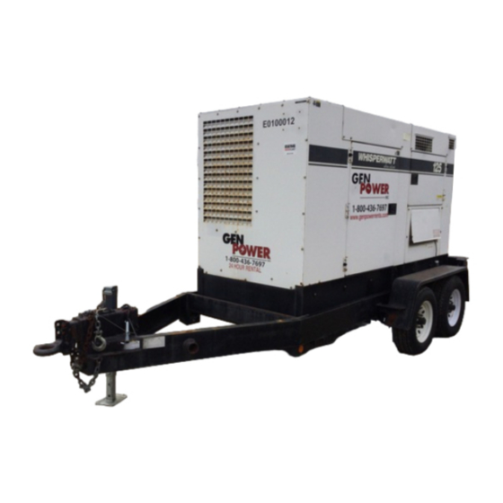
- Page 16 Also check the tire tread wear on both vehicles. ■ DO NOT transport generator with fuel in tank. ■ ALWAYS make sure the trailer is equipped with a "Safety Chain". Figure 3. Generator with Trailer PAGE 16 — DCA-125USJ — OPERATION AND PARTS MANUAL — REV. #0 (06/24/04)
-
Page 17: Trailer Specifications
(empty). 4. Frame Length - Measurement is from the ball hitch to the rear bumper (reflector). DCA-125USJ — OPERATION AND PARTS MANUAL — REV. #0 (06/24/04) — PAGE 17... -
Page 18: Generator Decals
DCA-125USJ — GENERATOR DECALS The DCA-125USJ generator is equipped with a number of safety decals (Figure 4). These decals are provided for operator safety and maintenance information. The illustration below and on the preceding page show the decals as they appear on the machine. -
Page 19: Generator Decals
DCA-125USJ — GENERATOR DECALS Figure 4. Generator Decals (Cont.) DCA-125USJ — OPERATION AND PARTS MANUAL — REV. #0 (06/24/04) — PAGE 19... -
Page 20: General Information
Use the cable selection chart (Table 5) as a guide Five output terminal lugs (3Ø power) for selecting proper extension cable size. Battery Charger (Optional) Water Heater (Optional) PAGE 20 — DCA-125USJ — OPERATION AND PARTS MANUAL — REV. #0 (06/24/04) - Page 21 Figure 5. Major Components DCA-125USJ — OPERATION AND PARTS MANUAL — REV. #0 (06/24/04) — PAGE 21...
- Page 22 NOTE PAGE PAGE 22 — DCA-125USJ — OPERATION AND PARTS MANUAL — REV. #0 (06/24/04)
- Page 23 (ON). be switched off. Voltage Regulator Control – Allows ±15% manual adjustment of the generator’s output voltage. DCA-125USJ — OPERATION AND PARTS MANUAL — REV. #0 (06/24/04) — PAGE 23...
- Page 24 DCA-125USJ — ENGINE OPERATING PANEL Figure 7. Engine Operating Panel PAGE 24 — DCA-125USJ — OPERATION AND PARTS MANUAL — REV. #0 (06/24/04)
- Page 25 Engine Running – Indicates that engine is running at controller will evaluate the fault a safe operating speed. and all major faults will shutdown the generator. DCA-125USJ — OPERATION AND PARTS MANUAL — REV. #0 (06/24/04) — PAGE 25...
-
Page 26: Output Terminal Panel Connections
Two (2) GFCI Circuit Breakers @ 20 amps considered bonded grounds . Five (5) Output Terminal Lugs ( U, V, W, O, Ground) Figure 8. Output Terminal Panel PAGE 26 — DCA-125USJ — OPERATION AND PARTS MANUAL — REV. #0 (06/24/04) - Page 27 240/120 position. Figure 12. Plastic Face Plate (Output Terminal Lugs) Figure 10. 120/240V Twist-Lock Auxiliary Receptacles DCA-125USJ — OPERATION AND PARTS MANUAL — REV. #0 (06/24/04) — PAGE 27...
- Page 28 The over current relay is lo- THIS fuse cated in the control box. Figure 14. Over Current Relay PAGE 28 — DCA-125USJ — OPERATION AND PARTS MANUAL — REV. #0 (06/24/04)
- Page 29 . t f . t f . t f building’s electrical system may occur t l u o r f t l o without this transfer switch. DCA-125USJ — OPERATION AND PARTS MANUAL — REV. #0 (06/24/04) — PAGE 29...
- Page 30 ) e l ) e l PAGE 30 — DCA-125USJ — OPERATION AND PARTS MANUAL — REV. #0 (06/24/04)
-
Page 31: Generator Outputs
AC Voltmeter Change-Over Switch to W-U and read the AC Voltmeter Gauge . Figure 18. AC Voltmeter Figure 19. AC Voltmeter Gauge Change-Over Switch (Volt reading on W-U Lug) DCA-125USJ — OPERATION AND PARTS MANUAL — REV. #0 (06/24/04) — PAGE 31... -
Page 32: Output Terminal Panel Connections
3. Turn the voltage regulator knob (Figure 23) clockwise to position and the voltage increase voltage output, turn counterclockwise to regulator must be adjusted to decrease voltage output. 208V. Figure 24. Voltage Regulator Knob (139V/240V) PAGE 32 — DCA-125USJ — OPERATION AND PARTS MANUAL — REV. #0 (06/24/04) -
Page 33: Output Terminal Panel Connections
3. Turn the voltage regulator knob (Figure 25) clockwise to increase voltage output, turn counterclockwise to increase voltage output, turn counterclockwise to decrease voltage output. decrease voltage output. DCA-125USJ — OPERATION AND PARTS MANUAL — REV. #0 (06/24/04) — PAGE 33... -
Page 34: Pre Setup
API Service Classification CC/SC immediately. API Service Classification CC/SD API Service Classification CC/SE API Service Classification CC/SF Table 10. Recommended Motor Oil OIL: SAE Figure 32. Internal Fuel Tank System PAGE 34 — DCA-125USJ — OPERATION AND PARTS MANUAL — REV. #0 (06/24/04) - Page 35 WARNING: WARNING: WARNING: WARNING: WARNING: DO NOT OVER-FILL fuel system. Leave room for fuel expansion . Fuel expands when heated (Figure 36). Figure 36. Fuel Expansion DCA-125USJ — OPERATION AND PARTS MANUAL — REV. #0 (06/24/04) — PAGE 35...
- Page 36 F - C ° F ° PAGE 36 — DCA-125USJ — OPERATION AND PARTS MANUAL — REV. #0 (06/24/04)
- Page 37 Tighten all hose clamps and check hoses for leaks. If any hose ( fuel or oil ) lines are defective replace them immediately. Figure 38. Battery Connections DCA-125USJ — OPERATION AND PARTS MANUAL — REV. #0 (06/24/04) — PAGE 37...
-
Page 38: Generator Start-Up Procedure (Manual)
3. The output terminal lugs are protected by a plastic cover. Remove this cover to gain access to the terminals. Tighten terminal nuts securely to prevent load wires from slipping out. PAGE 38 — DCA-125USJ — OPERATION AND PARTS MANUAL — REV. #0 (06/24/04) - Page 39 When a load is applied, LED (ON) the ammeter will indicate the amount of current that the load is drawing from the generator. Figure 48. Ammeter (No Load) DCA-125USJ — OPERATION AND PARTS MANUAL — REV. #0 (06/24/04) — PAGE 39...
-
Page 40: Generator Start-Up Procedure (Manual)
Under normal operating conditions this speed is approximately 1800 RPM’s. Figure 53. Ammeter (Load) 17. The generator will run until manually stopped or an abnormal condition occurs. Figure 51. Engine Tachometer Gauge PAGE 40 — DCA-125USJ — OPERATION AND PARTS MANUAL — REV. #0 (06/24/04) -
Page 41: Generator Start-Up Procedure (Auto Mode)
1. Perform steps 1 through 5 in the Before Starting section as outlined in the Manual Starting Procedure . DCA-125USJ — OPERATION AND PARTS MANUAL — REV. #0 (06/24/04) — PAGE 41... -
Page 42: Generator Shut-Down Procedure
Figure 55. MPEC Control Switch (Off/Reset) 5. Verify that the all status LED on the MPEC display are OFF (not lit). 6. Remove all loads from the generator. PAGE 42 — DCA-125USJ — OPERATION AND PARTS MANUAL — REV. #0 (06/24/04) -
Page 43: Maintenance
This can be reduced by keeping the tank full with diesel fuel. DCA-125USJ — OPERATION AND PARTS MANUAL — REV. #0 (06/24/04) — PAGE 43... - Page 44 If generator is mounted on a trailer, jack trailer up and place on blocks so tires do not touch the ground or block and completely remove the tires. PAGE 44 — DCA-125USJ — OPERATION AND PARTS MANUAL — REV. #0 (06/24/04)
-
Page 45: Maintenance
Figure 56. DCA-45SIU2 Battery Charger & Jacket Water Heater Power Connections DCA-125USJ — OPERATION AND PARTS MANUAL — REV. #0 (06/24/04) — PAGE 45... -
Page 46: Trailer Brakes Maintenance
. d i PAGE 46 — DCA-125USJ — OPERATION AND PARTS MANUAL — REV. #0 (06/24/04) -
Page 47: Trailer Maintenance
Flat Spots tire skidding. possible and adjust brakes. CAUTION: ALWAYS wear safety glasses when removing or installing force fitted parts. Failure to comply may result in serious injury. DCA-125USJ — OPERATION AND PARTS MANUAL — REV. #0 (06/24/04) — PAGE 47... -
Page 48: Trailer Maintenance
" 3 " 4 " 5 " 6 Figure 59. Wheel Lug Nuts Tightening Sequence NEVER use an pneumatic air NOTE gun to tighten wheel lug nuts. PAGE 48 — DCA-125USJ — OPERATION AND PARTS MANUAL — REV. #0 (06/24/04) -
Page 49: Trailer Wiring Diagram
DCA-125USJ — TRAILER WIRING DIAGRAM Figure 60. Trailer/Towing Vehicle Wiring Diagram DCA-125USJ — OPERATION AND PARTS MANUAL — REV. #0 (06/24/04) — PAGE 49... -
Page 50: Generator Wiring Diagram
DCA-125USJ — GENERATOR WIRING DIAGRAM Figure 61. Generator Wiring Diagram PAGE 50 — DCA-125USJ — OPERATION AND PARTS MANUAL — REV. #0 (06/24/04) -
Page 51: Engine Wiring Diagram
DCA-125USJ — ENGINE WIRING DIAGRAM Figure 62. Engine Wiring Diagram DCA-125USJ — OPERATION AND PARTS MANUAL — REV. #0 (06/24/04) — PAGE 51... - Page 52 PAGE 52 — DCA-125USJ — OPERATION AND PARTS MANUAL — REV. #0 (06/24/04)
-
Page 53: Engine Controller Troubleshooting
) s ( c i t k c i t r i c i t k c i DCA-125USJ — OPERATION AND PARTS MANUAL — REV. #0 (06/24/04) — PAGE 53... -
Page 54: Explanation Of Code In Remarks Column
NOTE one listed indicates newest (or latest) part available. NOTE The contents of this catalog are subject to change without notice . PAGE 54 — DCA-125USJ — OPERATION AND PARTS MANUAL — REV. #0 (06/24/04) -
Page 55: Suggested Spare Parts
1 ....0602123261 ......UNIT, WATER TEMPERATURE Part number on this Suggested Spare Parts list may supercede/replace the P/N shown NOTE in the text pages of this book. DCA-125USJ — OPERATION AND PARTS MANUAL — REV. #0 (06/24/04) — PAGE 55... - Page 56 DCA-125USJ — GENERATOR ASSY. GENERATOR ASSY. PAGE 56 — DCA-125USJ — OPERATION AND PARTS MANUAL — REV. #0 (06/24/04)
- Page 57 SPRING WASHER 0070506306 BEARING, 6306ZZ 0012810030 HEX, HEAD BOLT 0012810030 HEX, HEAD BOLT 8131332014 COVER, FAN 0600815000 0605000063 RUBBER SUSPENSION, KA120SS 0030016000 HEX, NUT 0040016000 SPRING WASHER DCA-125USJ — OPERATION AND PARTS MANUAL — REV. #0 (06/24/04) — PAGE 57...
- Page 58 DCA-125USJ — CONTROL BOX ASSY. CONTROL BOX ASSY. PAGE 58 — DCA-125USJ — OPERATION AND PARTS MANUAL — REV. #0 (06/24/04)
- Page 59 AC AMMETER ..........1 ... ACF-6 0~200A/400A:5A 0601801040 CHANGE-OVER SWITCH, AMMETER ..... 1 ... SL-2AS 0601806859 AC VOLTMETER ..........1 ... SCF-6 0~600V 0601801041 CHANGE-OVER SWITCH, VOLTMETER ..1 ... SL-2VS DCA-125USJ — OPERATION AND PARTS MANUAL — REV. #0 (06/24/04) — PAGE 59...
- Page 60 DCA-125USJ — CONTROL BOX ASSY. CONTROL BOX ASSY. PAGE 60 — DCA-125USJ — OPERATION AND PARTS MANUAL — REV. #0 (06/24/04)
- Page 61 WIRE HARNESS, FUEL LEAK ......1 ... 8400041~ 0601802149 FUSE ..............2 ... F-106510A 0601823240 RECTIFIER ............1 ... DE4503 0602103092 ALARM LAMP, PL095 ........1 ... 8400041~ 0601810245 BULB ..............1 ... 8400041~ DCA-125USJ — OPERATION AND PARTS MANUAL — REV. #0 (06/24/04) — PAGE 61...
- Page 62 DCA-125USJ — ENGINE AND RADIATOR ASSY. ENGINE AND RADIATOR ASSY. PAGE 62 — DCA-125USJ — OPERATION AND PARTS MANUAL — REV. #0 (06/24/04)
- Page 63 ELEMENT, AIR CLEANER ........1 ..P778214 0602040650 INDICATOR, AIR CLEANER ......... 1 ..RBXO0-2252 0602040596 BAND, AIR CLEANER 0016908020 HEX, HEAD BOLT 0207008000 HEX, NUT M3373100003 HOSE, AIR CLEANER 0605515146 HOSE BAND DCA-125USJ — OPERATION AND PARTS MANUAL — REV. #0 (06/24/04) — PAGE 63...
- Page 64 DCA-125USJ — ENGINE AND RADIATOR ASSY. ENGINE & RADIATOR ASSY. PAGE 64 — DCA-125USJ — OPERATION AND PARTS MANUAL — REV. #0 (06/24/04)
- Page 65 0602202592 RELAY ............... 1 ... AT141011 0027106016 MACHINE SCREW 0030006000 HEX, NUT 0017112025 HEX, HEAD BOLT 0040512000 TOOTHED WASHER 0602122281 SENDER, OIL PRESSURE 0602123282 SENDER, WATER PRESSURE DCA-125USJ — OPERATION AND PARTS MANUAL — REV. #0 (06/24/04) — PAGE 65...
- Page 66 DCA-125USJ — OUTPUT TERMINAL ASSY. OUTPUT TERMINAL ASSY. PAGE 66 — DCA-125USJ — OPERATION AND PARTS MANUAL — REV. #0 (06/24/04)
- Page 67 WHEN ORDERING ANY PAINTED PANEL TO INDICATE COLOR OF UNIT: 1-ORANGE 5-BLACK 2-WHITE 6-CATERPILLAR YELLOW 3-SPECTRUM GREY 7-CATO GOLD 4-SUNBELT GREEN 8-RED THE SERIAL NUMBER MAY BE REQUIRED. DCA-125USJ — OPERATION AND PARTS MANUAL — REV. #0 (06/24/04) — PAGE 67...
- Page 68 DCA-125USJ — BATTERY ASSY. BATTERY ASSY. PAGE 68 — DCA-125USJ — OPERATION AND PARTS MANUAL — REV. #0 (06/24/04)
- Page 69 BATTERY CABLE M3346901004 BATTERY CABLE CABLE ............1 ..... MAKE LOCALLY 0030012000 HEX, NUT 0040012000 SPRING WASHER 0017112025 HEX, HEAD BOLT 0040512000 TOOTHED WASHER 0040520000 TOOTHED WASHER DCA-125USJ — OPERATION AND PARTS MANUAL — REV. #0 (06/24/04) — PAGE 69...
- Page 70 DCA-125USJ — MUFFLER ASSY. MUFFLER ASSY. PAGE 70 — DCA-125USJ — OPERATION AND PARTS MANUAL — REV. #0 (06/24/04)
- Page 71 0017110035 HEX, HEAD BOLT ..........4 ... S/N 8500015~ M3333000803 EXHAUST PIPE 0016908055 HEX, HEAD BOLT 0017110050 HEX, HEAD BOLT ..........4 ... S/N 8500015~ 0602325066 CLAMP DCA-125USJ — OPERATION AND PARTS MANUAL — REV. #0 (06/24/04) — PAGE 71...
- Page 72 DCA-125USJ — FUEL TANK ASSY. FUEL TANK ASSY. PAGE 72 — DCA-125USJ — OPERATION AND PARTS MANUAL — REV. #0 (06/24/04)
- Page 73 PLAIN WASHER 0191302500 VENT HOSE 0605515109 HOSE BAND 0191301200 SUCTION HOSE 0191301200 RETURN HOSE 0605515109 HOSE BAND 0602042601 RETURN PIPE ..........1 ... RE67050 0222101000 TANK SHEET DCA-125USJ — OPERATION AND PARTS MANUAL — REV. #0 (06/24/04) — PAGE 73...
- Page 74 NUMBER WHEN ORDERING ANY PAINTED PANEL TO INDICATE COLOR OF UNIT: 1-ORANGE 5-BLACK 2-WHITE 6-CATERPILLAR YELLOW 3-SPECTRUM GREY 7-CATO GOLD 4-SUNBELT GREEN 8-RED THE SERIAL NUMBER MAY BE REQUIRED. PAGE 74 — DCA-125USJ — OPERATION AND PARTS MANUAL — REV. #0 (06/24/04)
- Page 75 0019208020 HEX, HEAD BOLT ........... 26 ... S/N 8500041~ M3433000803 CENTER FRAME ..........1 ... S/N 8500001 TO 8500035 M3433000813 CENTER FRAME ..........1 ... S/N 8500036~ DCA-125USJ — OPERATION AND PARTS MANUAL — REV. #0 (06/24/04) — PAGE 75...
- Page 76 NUMBER WHEN ORDERING ANY PAINTED PANEL TO INDICATE COLOR OF UNIT: 1-ORANGE 5-BLACK 2-WHITE 6-CATERPILLAR YELLOW 3-SPECTRUM GREY 7-CATO GOLD 4-SUNBELT GREEN 8-RED THE SERIAL NUMBER MAY BE REQUIRED. PAGE 76 — DCA-125USJ — OPERATION AND PARTS MANUAL — REV. #0 (06/24/04)
- Page 77 HEX, HEAD BOLT ..........2 ... S/N 8500001 TO 8500035 0605503062 FUEL LEAK DETECTION SWITCH ....1 ... S/N 840003~ M1414800104 BRACKET ............1 ... S/N 840003~ 0017108020 HEX HEAD BOLT ..........2 ... S/N 840003~ DCA-125USJ — OPERATION AND PARTS MANUAL — REV. #0 (06/24/04) — PAGE 77...
- Page 78 NUMBER WHEN ORDERING ANY PAINTED PANEL TO INDICATE COLOR OF UNIT: 1-ORANGE 5-BLACK 2-WHITE 6-CATERPILLAR YELLOW 3-SPECTRUM GREY 7-CATO GOLD 4-SUNBELT GREEN 8-RED THE SERIAL NUMBER MAY BE REQUIRED. PAGE 78 — DCA-125USJ — OPERATION AND PARTS MANUAL — REV. #0 (06/24/04)
- Page 79 WASHER 0016908020 HEX, HEAD BOLT ........... 26 ... S/N 8500001 TO 8500040 0019208020 HEX, HEAD BOLT ........... 26 ... S/N 8500041~ 0601850097 STOPPER 0027208025 MACHINE SCREW M9310000004 DCA-125USJ — OPERATION AND PARTS MANUAL — REV. #0 (06/24/04) — PAGE 79...
- Page 80 DCA-125USJ — RUBBER SEALS ASSY. RUBBER SEALS ASSY. PAGE 80 — DCA-125USJ — OPERATION AND PARTS MANUAL — REV. #0 (06/24/04)
- Page 81 0228900565 RUBBER SEAL 0228900945 RUBBER SEAL 0228800505 RUBBER SEAL 0229201200 RUBBER SEAL 0228800635 RUBBER SEAL 0228800970 RUBBER SEAL 0228800595 RUBBER SEAL 0228100640 RUBBER SEAL 0228100370 RUBBER SEAL DCA-125USJ — OPERATION AND PARTS MANUAL — REV. #0 (06/24/04) — PAGE 81...
-
Page 82: Nameplate And Decals
DCA-125USJ — NAMEPLATE AND DECALS ASSY. NAMEPLATE AND DECALS ASSY. PAGE 82 — DCA-125USJ — OPERATION AND PARTS MANUAL — REV. #0 (06/24/04) - Page 83 STRIPE 0600500092 PLATE, MQ POWER ......... 1 ... S/N 8400031~ 0021106016 MACHINE SCREW ..........4 ... S/N 8400031~ M9510100304 DECAL, ENVIRONMENTAL WARNIN6 ....1 ... S/N 8400031~ DCA-125USJ — OPERATION AND PARTS MANUAL — REV. #0 (06/24/04) — PAGE 83...
-
Page 84: Terms And Condition Of Sale - Parts
Freight is at the sender’s expense. All that date will be billed at the revised price. parts must be returned freight prepaid to Multiquip’s designated receiving point. PAGE 84 — DCA-125USJ — OPERATION AND PARTS MANUAL — REV. #0 (06/24/04) - Page 85 NOTE PAGE DCA-125USJ — OPERATION AND PARTS MANUAL — REV. #0 (06/24/04) — PAGE 85...
- Page 86 PARTS AND OPERATION MANUAL OPERATION AND PARTS MANUAL HERE'S HOW TO GET HELP PLEASE HAVE THE MODEL AND SERIAL NUMBER ON-HAND WHEN CALLING MQ POWER CORPORATE OFFICE 18910 Wilmington Ave. 800-421-1244 Carson, CA 90746 FAX: 310-632-2656 Email: mqpower@multiquip.com Internet: www.mqpower.com...
Need help?
Do you have a question about the DCA-125USJ and is the answer not in the manual?
Questions and answers