MQ Power WHISPERWATT Series Operation Manual
60hz generator
Hide thumbs
Also See for WHISPERWATT Series:
- Operation manual (114 pages) ,
- Operation and parts manual (82 pages) ,
- Instruction manual (118 pages)
Table of Contents
Advertisement
Advertisement
Table of Contents
Troubleshooting

Related Manuals for MQ Power WHISPERWATT Series


Summary of Contents for MQ Power WHISPERWATT Series
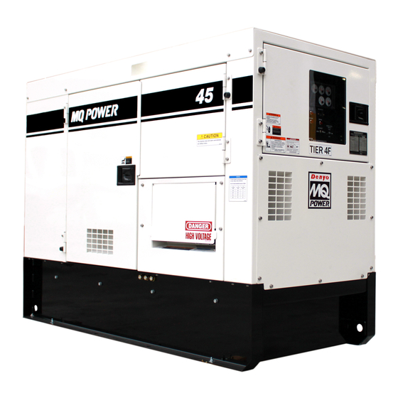
- Page 1 OPERATION MANUAL WHISPERWATT™ SERIES MODEL DCA45SSIU4F 60Hz GENERATOR (ISUZU 4LE2X DIESEL ENGINE) Revision #5 (02/28/20) To find the latest revision of this publication or associated parts manual, visit our website at: www.mqpower.com THIS MANUAL MUST ACCOMPANY THE EQUIPMENT AT ALL TIMES.
-
Page 2: Proposition 65 Warning
PROPOSITION 65 WARNING PAGE 2 — DCA45SSIU4F 60 HZ GENERATOR • OPERATION MANUAL — REV. #5 (02/28/20) -
Page 3: Table Of Contents
TABLE OF CONTENTS DCA45SSIU4F 60 Hz Generator Proposition 65 Warning ........... 2 Table of Contents ............. 3 Safety Information ..........4–9 Specifications ............10 Dimensions ............11 Installation ............12–13 General Information ..........14 Major Components ..........15 Engine/Generator Control Panel...... 16–17 Output Terminal Panel Familiarization ..... -
Page 4: Safety Information
SAFETY INFORMATION Do not operate or service the generator before reading the Potential hazards associated with the operation of this entire manual. Safety precautions should be followed at all generator will be referenced with hazard symbols which times when operating this generator. Failure to read and may appear throughout this manual in conjunction with understand the safety messages and operating instructions safety messages. - Page 5 NEVER use accessories or attachments that are not being used. The generator should be stored in a clean, dry location out of the reach of children and unauthorized recommended by MQ Power for this generator. Damage to the generator and/or injury to the user may result. personnel.
- Page 6 SAFETY INFORMATION ENGINE SAFETY Operation of the generator may create sparks that can start fi res around dry vegetation. A spark arrestor DANGER may be required. The operator should contact local fi re agencies for laws or regulations relating to fi re prevention ...
- Page 7 SAFETY INFORMATION State Health Safety Codes and Public Resources Refer to the MQ Power trailer manual for additional safety Codes specify that in certain locations, spark arresters information. must be used on internal combustion engines that use In order to reduce the possibility of an accident hydrocarbon fuels.
- Page 8 SAFETY INFORMATION Raise and lock the trailer wheel stand in the upright NEVER use damaged or worn cables or cords when position when towing. connecting equipment to the generator. Inspect the insulation for cuts. Place chock blocks underneath the wheels to prevent rolling while parked.
- Page 9 SAFETY INFORMATION ALWAYS keep the battery charged. If the battery is not Metal recycling involves the collection of metal from charged, combustible gas will build up. discarded products and its transformation into raw materials to use in manufacturing a new product. ...
-
Page 10: Specifications
SPECIFICATIONS Table 1. Generator Specifications Model DCA45SSIU4F Type Revolving field, self-ventilated, protected type synchronous generator Armature Connection Star with Neutral Zigzag Phase 3Ø 1Ø Standby Output 39.6 kW (49.5 kVA) 28.8 kW Prime Output 36 kW (45 kVA) 26 kW 3Ø... -
Page 11: Dimensions
DIMENSIONS MAXIMUM LIFTING POINT TOP VIEW 6,960 lb. (3,157 kg) SIDE VIEW FRONT VIEW Figure 1. Dimensions Table 3. Dimensions Reference Dimension in. (mm) Reference Letter Dimension in. (mm) Letter 28.34 (720) 26.18 (665) 28.34 (720) 83.86 (2,130) 26.18 (665) 61.02 (1,550) 32.28 (820) 37.40 (950) -
Page 12: Installation
M I N 2 . 4 T . / REFERENCE NEC 250 Figure 2. Typical Generator Grounding Application NOTICE Trailer-mounted generators are the sole responsibility of MQ Power. PAGE 12 — DCA45SSIU4F 60 HZ GENERATOR • OPERATION MANUAL — REV. #5 (02/28/20) - Page 13 INSTALLATION OUTDOOR INSTALLATION GENERATOR GROUNDING NOTICE Install the generator in an area that is free of debris, bystanders, and overhead obstructions. Make sure the The Occupational Safety and Health Administration generator is on secure, level ground so that it cannot slide (OSHA) and the National Electrical Code (NEC) or shift around.
-
Page 14: General Information
„ 3-Pole, 110-amp Main Circuit Breaker Reference Table 2 for engine specifications. „ “Control Box” (located behind Control Panel) In keeping with MQ Power’s policy of constantly improving • Automatic Voltage Regulator its products, the specifications quoted herein are subject •... -
Page 15: Major Components
MAJOR COMPONENTS Table 4. Generator Major Components Intergrated Gauge Control Low Oil Pressre High temp. Over Crank Over Speed Engine Started ITEM NO. DESCRIPTION DOC Assembly Voltage Selector Switch Assembly Output Terminal Assembly Generator Assembly Output Receptacles Assembly Engine Assembly Battery Assembly Oil Drain Coolant Drain... -
Page 16: Engine/Generator Control Panel
ENGINE/GENERATOR CONTROL PANEL Integrated Gauge Control OIL PRESS Low Oil Pressure High Temp Over Crank Over Speed n/min n/min Engine Integrated Gauge Control Started Fuel Low Oil Pressure High Temp Over Crank Over Speed n/min n/min Engine Started Fuel Figure 4. Engine/Generator Control Panel F. - Page 17 ENGINE/GENERATOR CONTROL PANEL 4. Frequency Meter — Indicates the output frequency in hertz (Hz). Normally 60 Hz. 5. AC Ammeter — Indicates the amount of current the load is drawing from the generator per leg selected by the ammeter phase-selector switch. 6.
-
Page 18: Output Terminal Panel Familiarization
OUTPUT TERMINAL PANEL FAMILIARIZATION OUTPUT TERMINAL PANEL OUTPUT TERMINAL FAMILIARIZATION The Output Terminal Panel (Figure 5) shown below is The “Output Terminal Panel” (Figure 5) is provided with located on the right-hand side (left from the control panel) the following: of the generator. - Page 19 OUTPUT TERMINAL PANEL FAMILIARIZATION 120 VAC GFCI Receptacles Each auxiliary receptacle is protected by a 50-amp circuit breaker. These breakers are located directly above the NOTICE GFCI receptacles. Remember the load output (current) on It is recommended that the GFCI receptacles be tested both receptacles is dependent on the load requirements of when the generator is initially uncrated.
- Page 20 OUTPUT TERMINAL PANEL FAMILIARIZATION Connecting Loads Overcurrent Relay An overcurrent relay (Figure 11) is connected to the main Loads can be connected to the generator by various methods, output terminal lugs, camlocks or the convenience circuit breaker. In the event of an overload, both the circuit receptacles (Figure 10).
-
Page 21: Load Application
LOAD APPLICATION SINGLE-PHASE LOAD THREE-PHASE LOAD Always be sure to check the nameplate on the generator When calculating the power requirements for 3-phase and equipment to ensure the wattage, amperage, frequency, power use the following equation: and voltage requirements are satisfactorily supplied by the VOLTAGE ×... -
Page 22: Generator Outputs
GENERATOR OUTPUTS GENERATOR OUTPUT VOLTAGES Maximum Amps Table 8 shows the maximum amps the generator can A wide range of voltages are available to supply voltage for many different applications. Voltages are selected by using provide. DO NOT exceed the maximum amps as listed. the voltage selector switch (Figure 12). -
Page 23: Generator Outputs/Gauge Reading
GENERATOR OUTPUTS/GAUGE READING HOW TO READ THE AC AMMETER AC Ammeter Gauge Reading AND AC VOLTMETER GAUGES Place the AC Ammeter Change-Over Switch (Figure 16) in the U position and observe the current reading (load The AC ammeter and AC voltmeter gauges are controlled drain) on the U terminal as indicated on the AC Ammeter by the AC ammeter and AC voltmeter change-over switches. -
Page 24: Output Terminal Panel Connections
OUTPUT TERMINAL PANEL CONNECTIONS UVWO TERMINAL OUTPUT VOLTAGES 3. Turn the voltage regulator knob (Figure 20) clockwise to increase voltage output, turn counterclockwise to Various output voltages can be obtained using the UVWO decrease voltage output. Use the voltage regulator output terminal lugs. - Page 25 OUTPUT TERMINAL PANEL CONNECTIONS 3Ø-480/277V UVWO Terminal Output Voltages 1Ø-240/120V UVWO Terminal Output Voltages 1. Place the voltage selector switch in the 3Ø 480/277 1. Place the voltage selector switch in the 1Ø 240/120 position as shown in Figure 22. position as shown in Figure 24.
-
Page 26: Inspection/Setup
INSPECTION/SETUP ENGINE OIL CHECK 5. If the engine oil level is low (Figure 27C), remove the oil filler cap (Figure 28) and fill to a safe operating level NOTICE (max) as indicated by the dipstick (Figure 27A). This Isuzu engine is equipped with a low oil shutdown NOTICE capability. - Page 27 INSPECTION/SETUP FUEL CHECK REFUELING PROCEDURE: WARNING DANGER Diesel fuel and its vapors are dangerous Fuel spillage on a hot engine can cause to your health and the surrounding a fire or explosion. If fuel spillage occurs, environment. Avoid skin contact and/or wipe up the spilled fuel completely to inhaling fumes.
- Page 28 INSPECTION/SETUP 3. NEVER overfill the fuel tank — It is important to read NOTICE the fuel gauge when filling the trailer fuel tank. DO NOT Normally, only the coolant level in the recovery tank wait for fuel to rise in the filler neck (Figure 32). needs to be checked.
- Page 29 INSPECTION/SETUP Cleaning the Radiator FAN BELT TENSION The engine may overheat if the radiator cooling fins A slack fan belt may contribute to overheating, or to (Figure 35) become overloaded with dust or debris. insufficient charging of the battery. Inspect the fan belt for Periodically clean the radiator fins with compressed air.
- Page 30 INSPECTION/SETUP BATTERY When connecting the battery do the following: 1. NEVER connect the battery cables to the battery This unit is of negative ground. DO NOT connect in reverse. terminals when the Auto-Off/Reset-Manual Switch Always maintain battery fluid level between the specified is in either the AUTO or MANUAL position.
-
Page 31: Generator Start-Up Procedure (Manual)
GENERATOR START-UP PROCEDURE (MANUAL) BEFORE STARTING STARTING (MANUAL) 1. Place the Auto-Off/Reset-Manual Switch in the CAUTION MANUAL position to start the engine (Figure 41). The engine’s exhaust contains harmful emissions. ALWAYS have adequate ventilation when operating. AUTO MANUAL Direct exhaust away from nearby personnel. OFF/RESET WARNING Figure 41. - Page 32 GENERATOR START-UP PROCEDURE (MANUAL) 4. The generator’s AC voltmeter (Figure 43) will display the generator’s output in VOLTS. °F WATER TEMP Figure 47. Coolant Temperature Gauge 9. The tachometer gauge (Figure 48) will indicate the Figure 43. Voltmeter speed of the engine when the generator is operating. Under normal operating conditions this speed is 5.
-
Page 33: Generator Start-Up Procedure (Auto Mode)
GENERATOR START-UP PROCEDURE (AUTO MODE) STARTING (AUTO MODE) When starting the generator in AUTO mode use the “Manual Start-Up” procedure except where noted (see DANGER below). Before connecting this generator to any 1. Perform steps 1 through 5 in the Before Starting section building’s electrical system, a licensed as outlined in the Manual Starting Procedure. -
Page 34: Generator Shutdown Procedure
GENERATOR SHUTDOWN PROCEDURE EMERGENCY SHUTDOWN PROCEDURE WARNING WARNING Place the MAIN, GFCI and LOAD circuit breakers as shown NEVER stop the engine suddenly except in an NEVER stop the engine suddenly except in an in Figure 52 to the OFF position. emergency. -
Page 35: Maintenance
MAINTENANCE 500 Hrs. 3,000 Hrs. 10 Hrs. Table 14. Inspection/Maintenance 250 Hrs. or Every or Every OTHER DAILY 12 Months 36 Months Check Engine Oil and Coolant Levels Check Fuel Filter/Water Separator Bowl Check Air Cleaner Check Air Cleaner Element Check for Leaks/Hoses/Clamps Check for Loosening of Parts Drain Water in Fuel... - Page 36 MAINTENANCE GENERAL INSPECTION NOTICE Prior to each use, the generator should be cleaned and Operating the engine with loose or damaged air cleaner inspected for deficiencies. Check for loose, missing or components could allow unfiltered air into the engine damaged nuts, bolts or other fasteners. Also check for causing premature wear and failure.
- Page 37 MAINTENANCE DRAINING THE FUEL FILTER ELEMENT FUEL FILTER ELEMENT REPLACEMENT NOTICE 1. Use a filter wrench to remove the element case (Figure 57) from the fuel filter body. Inspect the fuel filter daily. If the fuel filter (Figure 56) has collected a significant amount of water and sediment at the bottom of the cup, it should be drained off immediately.
- Page 38 MAINTENANCE ELECTROMAGNETIC FUEL PUMP (500 HOURS) DRAINING THE CONTAINMENT TANK The filter inside the fuel pump (Figure 58) is either a paper 1. This generator is equipped with an environmental type or steel mesh type depending on the fuel pump type. containment tank.
- Page 39 MAINTENANCE CLEANING INSIDE THE FUEL TANK Also, examine the belt and determine if it is oil soaked or “glazed ” (a hard shiny appearance on the sides of the belt). If necessary, drain the fuel inside the fuel tank completely. Either of these two conditions can cause the belt to run hot, Using a spray washer (Figure 60) wash out any deposits which can weaken it and increase the danger of it breaking.
- Page 40 MAINTENANCE DRAINING ENGINE COOLANT 5. After the engine oil has been completely drained, reinstall the oil drain cap and tighten securely. WARNING 6. Place the oil drain valve in the CLOSED position. DO NOT remove the pressure cap from the radiator ENGINE OIL FILTER REPLACEMENT when the engine is hot! Wait until the coolant temperature is below 120°F (50°C) before removing...
- Page 41 MAINTENANCE FLUSHING OUT THE RADIATOR TESTING THE GFCI RECEPTACLE AND REPLACING COOLANT NOTICE „ Open both cocks located at the crankcase side and at The GFCI receptacle is designed to interrupt power the lower part of the radiator and drain the coolant. Open when a ground fault exists to prevent injuries and shock the radiator cap while draining.
- Page 42 MAINTENANCE GENERATOR STORAGE 4. Plug a power tool into the GFCI receptacle such as an electric drill (Figure 69). Squeeze the ON/OFF switch For long-term storage of the generator the following is on the drill and verify that the drill turns on. recommended: „...
- Page 43 MAINTENANCE JACKET WATER HEATER AND When using the generator in hot climates there is no reason to apply power to the jacket water heater. However, if the INTERNAL BATTERY CHARGER generator will be used in cold climates it is always a good 120 VAC INPUT RECEPTACLES (OPTIONAL) idea to apply power to the jacket water heater at all times.
- Page 44 MAINTENANCE EMISSION CONTROL EMISSION CARBON CHECK The emission control system employed with the Isuzu Deposition of carbon (soot, unburned fuel) in the exhaust 4LE2T diesel engine consists of a Diesel Oxidation Catalyst pipe line and muffler could cause not only system derates (DOC).
-
Page 45: Troubleshooting (Diagnostics)
TROUBLESHOOTING (DIAGNOSTICS) The engine controller of this generator diagnoses problems 6. Verify that the diagnostic lamp is ON. This indicates (faults/errors) that arise from the engine control system and that there is a fault/error in the engine or the engine the engine itself. -
Page 46: Troubleshooting (Generator)
TROUBLESHOOTING (GENERATOR) Practically all breakdowns can be prevented by proper handling and maintenance inspections, but in the event of a breakdown, use Table 15 shown below for diagnosis of the generator. If the problem cannot be remedied, consult our company’s business office or service plant. Table 15. -
Page 47: Troubleshooting (Engine)
TROUBLESHOOTING (ENGINE) Troubleshooting (Engine) Symptom Possible Problem Solution No Fuel reaching injection pump? Add fuel. Check entire fuel system. Defective fuel pump? Replace fuel pump. Fuel fi lter clogged? Replace fuel fi lter and clean tank. Faulty fuel supply line? Replace or repair fuel line. - Page 48 TROUBLESHOOTING (ENGINE) Troubleshooting (Engine) - continued Symptom Possible Problem Solution Air fi lter blocked? Clean or replace air fi lter. Low engine power output and low speed, Incorrect valve clearances? Adjust valves per engine specifi cation. black exhaust smoke. Malfunction at injector? See engine manual.
-
Page 49: Generator Wiring Diagram
GENERATOR WIRING DIAGRAM DCA45SSIU4F 60 HZ GENERATOR• OPERATION MANUAL — REV. #5 (02/28/20) — PAGE 49... -
Page 50: Engine Wiring Diagram S/N 7251795 And Below
ENGINE WIRING DIAGRAM (S/N 7251795 AND BELOW) PAGE 50 — DCA45SSIU4F 60 HZ GENERATOR • OPERATION MANUAL — REV. #5 (02/28/20) -
Page 51: Engine Wiring Diagram S/N 7251796 And Above
ENGINE WIRING DIAGRAM (S/N 7251796 AND ABOVE) DCA45SSIU4F 60 HZ GENERATOR• OPERATION MANUAL — REV. #5 (02/28/20) — PAGE 51... -
Page 52: Controller Wiring Diagram
CONTROLLER WIRING DIAGRAM PAGE 52 — DCA45SSIU4F 60 HZ GENERATOR • OPERATION MANUAL — REV. #5 (02/28/20) - Page 53 NOTES DCA45SSIU4F 60 HZ GENERATOR• OPERATION MANUAL — REV. #5 (02/28/20) — PAGE 53...
-
Page 54: Battery Charger Wiring Diagram
BATTERY CHARGER WIRING DIAGRAM BLACK 14 AWG. LINE (L)120VAC INPUT WHITE 14 AWG. NEUTRAL (N) GREEN 14 AWG. GROUND (G) TO CHASSIS GROUND GREEN 16 AWG. TO STARTER “B” TERMINAL RED 16 AWG. 120 VAC INPUT, INSERT EXTERNAL POWER CORD HERE. NOTES: NEMA 5-15, 15A, 120 VAC, P/N EE6176 (HBL5278C/HUBBLE RECEPTACLE). -
Page 55: Jacket Water Heater Wiring Diagram
JACKET WATER HEATER WIRING DIAGRAM BLACK 14 AWG. LINE (L)120VAC INPUT WHITE 14 AWG. NEUTRAL (N) GREEN 14 AWG. GROUND (G) BLOCK HEATER (P/N 44558) TEMP. BLACK 14 AWG. SWITCH LINE (L)120VAC INPUT HEATING 120 VAC ELEMENT WHITE 14 AWG. NEUTRAL (N) GREEN 14 AWG. - Page 56 © COPYRIGHT 2020, MULTIQUIP INC. Multiquip Inc , the MQ logo and the MQ Power logo are registered trademarks of Multiquip Inc. and may not be used, reproduced, or altered without written permission. All other trademarks are the property of their respective owners and used with permission.
Need help?
Do you have a question about the WHISPERWATT Series and is the answer not in the manual?
Questions and answers