Table of Contents
Advertisement
Advertisement
Table of Contents
Troubleshooting

Related Manuals for MQ Power DCA125USI


Summary of Contents for MQ Power DCA125USI
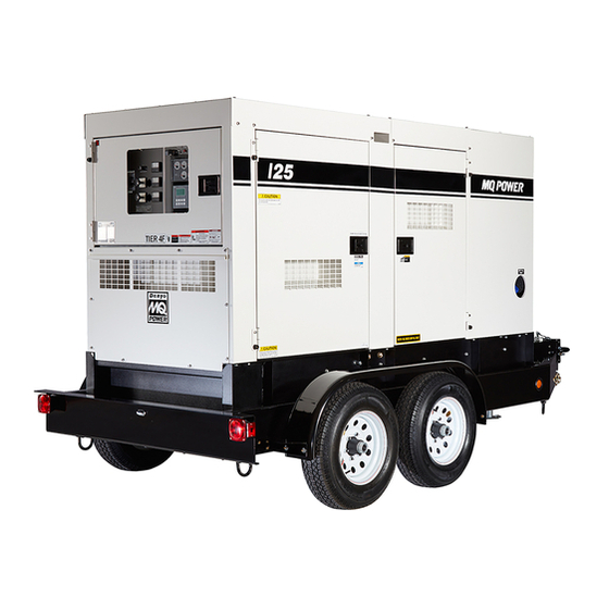
- Page 1 OPERATION AND PARTS MANUAL ® MODEL DCA125USI 60 HZ GENERATOR (ISUZU 4HK1X DIESEL ENGINE) Revision #1 (03/25/11) To fi nd the latest revision of this publication, visit our website at: www.multiquip.com THIS MANUAL MUST ACCOMPANY THE EQUIPMENT AT ALL TIMES.
-
Page 2: Proposition 65 Warning
PROPOSITION 65 WARNING Diesel engine exhaust and some of PAGE 2 — DCA125USI 60 HZ GENERATOR • OPERATION AND PARTS MANUAL — REV. #1 (03/25/11) -
Page 3: Reporting Safety Defects
1-888-327-4236 (TTY: 1-800-424-9153), go to http://www.nhtsa.dot.gov; or write to: Administrator NHTSA 1200 New Jersey Avenue S.E. Washington, DC 20590 You can also obtain information about motor vehicle safety from http://www.safecar.gov. DCA125USI 60 HZ GEN. • OPERATION AND PARTS MANUAL — REV. #1 (03/25/11) — PAGE 3... -
Page 4: Table Of Contents
Controller Wiring Diagram ........48 Troubleshooting (Generator) ........49 Troubleshooting (Diagnostic Lamp) ....... 50 Explanation Of Code In Remarks Column..... 52 Suggested Spare Parts ......... 53 PAGE 4 — DCA125USI 60 HZ GENERATOR • OPERATION AND PARTS MANUAL — REV. #1 (03/25/11) -
Page 5: Parts Ordering Procedures
All orders are treated as Standard Orders and will ship the same day if received prior to 3PM PST. WE ACCEPT ALL MAJOR CREDIT CARDS! DCA125USI 60 HZ GEN. • OPERATION AND PARTS MANUAL — REV. #1 (03/25/11) — PAGE 5... -
Page 6: Safety Information
CAUTION Indicates a hazardous situation which, if not avoided, COULD result in MINOR or MODERATE INJURY. NOTICE Addresses practices not related to personal injury. PAGE 6 — DCA125USI 60 HZ GENERATOR • OPERATION AND PARTS MANUAL — REV. #1 (03/25/11) - Page 7 ALWAYS store equipment properly when it is not being used. Equipment should be stored in a clean, dry location out of the reach of children and unauthorized personnel DCA125USI 60 HZ GEN. • OPERATION AND PARTS MANUAL — REV. #1 (03/25/11) — PAGE 7...
- Page 8 NEVER touch the hot exhaust manifold, local Health and Safety Administrator. muffl er or cylinder. Allow these parts to cool before servicing equipment. PAGE 8 — DCA125USI 60 HZ GENERATOR • OPERATION AND PARTS MANUAL — REV. #1 (03/25/11)
- Page 9 Use the trailer’s swivel jack to adjust the trailer height to ALWAYS shutdown engine before transporting a level position while parked. DCA125USI 60 HZ GEN. • OPERATION AND PARTS MANUAL — REV. #1 (03/25/11) — PAGE 9...
- Page 10 NEVER grab or touch a live power cord or cable with wet hands. The possibility exists of electrical shock, electrocution or death. PAGE 10 — DCA125USI 60 HZ GENERATOR • OPERATION AND PARTS MANUAL — REV. #1 (03/25/11)
- Page 11 ALWAYS disconnect the NEGATIVE battery terminal before performing service on the generator. ALWAYS keep battery cables in good working condition. Repair or replace all worn cables. DCA125USI 60 HZ GEN. • OPERATION AND PARTS MANUAL — REV. #1 (03/25/11) — PAGE 11...
-
Page 12: Specifi Cations
5.7 gal. (21.7 L)/hr at 3/4 load load Fuel Consumption 4.0 gal. (15.1 L)/hr at 1/2 2.4 gal. (9.1 L)/hr at 1/4 load load Battery 12V-128 Ah x 1 PAGE 12 — DCA125USI 60 HZ GENERATOR • OPERATION AND PARTS MANUAL — REV. #1 (03/25/11) -
Page 13: Dimensions
37.00 in. (940 mm.) 73.00 in. (1,855 mm.) 36.20 in. (920 mm.) 48.80 in. (1,200 mm.) 37.00 in. (940 mm.) 3620 in. (920 mm.) DCA125USI 60 HZ GEN. • OPERATION AND PARTS MANUAL — REV. #1 (03/25/11) — PAGE 13... -
Page 14: Installation
INSTALLATION Figure 2. Typical Generator Grounding Application PAGE 14 — DCA125USI 60 HZ GENERATOR • OPERATION AND PARTS MANUAL — REV. #1 (03/25/11) -
Page 15: Installation
They are to resist damage to the bottom of the generator and to maintain alignment. DCA125USI 60 HZ GEN. • OPERATION AND PARTS MANUAL — REV. #1 (03/25/11) — PAGE 15... -
Page 16: General Information
Use the cable selection chart (Table 6) as a Jacket Water Heater (Optional) guide for selecting proper extension cable size. Low Coolant Level Switch PAGE 16 — DCA125USI 60 HZ GENERATOR • OPERATION AND PARTS MANUAL — REV. #1 (03/25/11) -
Page 17: Major Components
Enclosure Assembly Generator Assembly Output Terminal Assembly Fuel Tank Assembly Battery Assembly Engine Operating Panel Assembly Generator Control Panel Assembly Figure 3. Major Components DCA125USI 60 HZ GEN. • OPERATION AND PARTS MANUAL — REV. #1 (03/25/11) — PAGE 17... -
Page 18: Generator Control Panel
7. AC Voltmeter — Indicates the output voltage present main circuit breaker in the closed position (ON). at the U,V, and W Output Terminal Lugs. PAGE 18 — DCA125USI 60 HZ GENERATOR • OPERATION AND PARTS MANUAL — REV. #1 (03/25/11) - Page 19 NOTES DCA125USI 60 HZ GEN. • OPERATION AND PARTS MANUAL — REV. #1 (03/25/11) — PAGE 19...
-
Page 20: Engine Operating Panel
ENGINE OPERATING PANEL Figure 5. Engine Operating Panel PAGE 20 — DCA125USI 60 HZ GENERATOR • OPERATION AND PARTS MANUAL — REV. #1 (03/25/11) -
Page 21: Engine Operating Panel
F. Engine Running — Indicates that engine is running controller will evaluate the fault at a safe operating speed. DCA125USI 60 HZ GEN. • OPERATION AND PARTS MANUAL — REV. #1 (03/25/11) — PAGE 21... -
Page 22: Output Terminal Panel Familiarization
Two GFCI Circuit Breakers @ 20 amps Five Output Terminal Lugs ( U, V, W, O, Ground) Figure 6. Output Terminal Panel PAGE 22 — DCA125USI 60 HZ GENERATOR • OPERATION AND PARTS MANUAL — REV. #1 (03/25/11) - Page 23 240/120 position. Figure 10. Plastic Face Plate (Output Terminal Lugs) Figure 8. 120/240V Twist-Lock Auxiliary Receptacles DCA125USI 60 HZ GEN. • OPERATION AND PARTS MANUAL — REV. #1 (03/25/11) — PAGE 23...
- Page 24 Make sure to switch ALL circuit breakers to the OFF position prior to starting the engine. Figure 12. Over Current Relay Figure 11. Connecting Loads PAGE 24 — DCA125USI 60 HZ GENERATOR • OPERATION AND PARTS MANUAL — REV. #1 (03/25/11)
-
Page 25: Load Application
1800 3600 150 ft. 100 ft. 65 ft. 2400 4800 125 ft. 75 ft. 50 ft. CAUTION: Equipment damage can result from low voltage DCA125USI 60 HZ GEN. • OPERATION AND PARTS MANUAL — REV. #1 (03/25/11) — PAGE 25... -
Page 26: Generator Outputs
127V 139V 240V 254V 277V 10 amps/receptacle Voltage Selector Switch Single-Phase 240/120V Position 15 amps/receptacle 1Ø Line-Neutral/ 120V 240V Line-Neutral Line-Line Line-Line 20 amps/receptacle PAGE 26 — DCA125USI 60 HZ GENERATOR • OPERATION AND PARTS MANUAL — REV. #1 (03/25/11) -
Page 27: Generator Outputs/Gauge Reading
W and U terminals as indicated on the AC Voltmeter Gauge (Figure 16) Figure 15. AC Voltmeter Figure 16. AC Voltmeter Change-Over Switch Gauge DCA125USI 60 HZ GEN. • OPERATION AND PARTS MANUAL — REV. #1 (03/25/11) — PAGE 27... -
Page 28: Output Terminal Panel Connections
To achieve a 3Ø 208V output the voltage selector switch Figure 20. UVWO Terminal Lugs must be in the 3Ø-240/139 position and the voltage 3Ø-240/139V Connections regulator must be adjusted to 208V. PAGE 28 — DCA125USI 60 HZ GENERATOR • OPERATION AND PARTS MANUAL — REV. #1 (03/25/11) - Page 29 ALWAYS make sure that the connections to the UVWO terminals are secure and tight. The possibility of arcing exists, that could cause a fi re. DCA125USI 60 HZ GEN. • OPERATION AND PARTS MANUAL — REV. #1 (03/25/11) — PAGE 29...
-
Page 30: Inspection/Setup
API Service Classifi cation CC/SD API Service Classifi cation CC/SE API Service Classifi cation CC/SF Table 11. Recommended Motor Oil Figure 29. Internal Fuel Tank System PAGE 30 — DCA125USI 60 HZ GENERATOR • OPERATION AND PARTS MANUAL — REV. #1 (03/25/11) - Page 31 ONLY use #2 diesel fuel when refueling. DO NOT OVERFILL fuel system. Leave room for fuel expansion. Fuel expands when heated (Figure 33). Figure 33. Fuel Expansion DCA125USI 60 HZ GEN. • OPERATION AND PARTS MANUAL — REV. #1 (03/25/11) — PAGE 31...
- Page 32 Freezing Point Vol % Anti-Freeze °C °F NOTICE When the antifreeze is mixed with water, the antifreeze mixing ratio must be less than 50%. PAGE 32 — DCA125USI 60 HZ GENERATOR • OPERATION AND PARTS MANUAL — REV. #1 (03/25/11)
- Page 33 Tighten all hose clamps and check hoses for leaks. Figure 35. Battery Connections If any hose (fuel or oil) lines are defective replace them immediately. DCA125USI 60 HZ GEN. • OPERATION AND PARTS MANUAL — REV. #1 (03/25/11) — PAGE 33...
-
Page 34: Generator Start-Up Procedure
5. Close all engine enclosure doors (Figure 37). Figure 41. MPEC Control Switch (Manual Position) CORRECT INCORRECT Figure 37. Engine Enclosure Doors PAGE 34 — DCA125USI 60 HZ GENERATOR • OPERATION AND PARTS MANUAL — REV. #1 (03/25/11) - Page 35 42 to 71 displaying the 60 cycle output frequency in HERTZ. psi. (290~490 kPa). Figure 49. Oil Pressure Gauge Figure 45. Frequency Meter DCA125USI 60 HZ GEN. • OPERATION AND PARTS MANUAL — REV. #1 (03/25/11) — PAGE 35...
-
Page 36: Generator Shut-Down Procedures
16. The generator will run until manually stopped or an 1. Place the MPEC Control Switch (Figure 56) in the abnormal condition occurs. OFF/RESET position. PAGE 36 — DCA125USI 60 HZ GENERATOR • OPERATION AND PARTS MANUAL — REV. #1 (03/25/11) -
Page 37: Maintenance
RED meaning the element needs changing or service. After changing the air element, press the dust indicator button to reset the indicator. DCA125USI 60 HZ GEN. • OPERATION AND PARTS MANUAL — REV. #1 (03/25/11) — PAGE 37... - Page 38 To restart after running out of fuel, turn the switch to the “ON” position for 15-30 seconds. Try again, if needed. Figure 58. Fuel Tank Cleaning PAGE 38 — DCA125USI 60 HZ GENERATOR • OPERATION AND PARTS MANUAL — REV. #1 (03/25/11)
- Page 39 Allow engine to cool when fl ushing out radiator. Flushing the radiator while hot could cause serious burns from water or steam. DCA125USI 60 HZ GEN. • OPERATION AND PARTS MANUAL — REV. #1 (03/25/11) — PAGE 39...
-
Page 40: Maintenance
To ensure adequate starting capability, always have power applied to the generator's internal battery charger.. Figure 60. Battery Charger & Jacket Water Heater Power Connections PAGE 40 — DCA125USI 60 HZ GENERATOR • OPERATION AND PARTS MANUAL — REV. #1 (03/25/11) -
Page 41: Trailer Maintenance
16. Application — Indicates which units can be employed on a particular trailer. 7. Coupler — Type of hitch used on the trailer for towing. DCA125USI 60 HZ GEN. • OPERATION AND PARTS MANUAL — REV. #1 (03/25/11) — PAGE 41... - Page 42 Dragging Brakes Replace rubber parts Enough brake fl uid or correct fl uid? fi ll with dot 4 fl uid. PAGE 42 — DCA125USI 60 HZ GENERATOR • OPERATION AND PARTS MANUAL — REV. #1 (03/25/11)
- Page 43 Align wheels. Check bearing adjustment Cupping Out-of-balance. and balance tires. Wheel lockup and Avoid sudden stops when Flat Spots tire skidding. possible and adjust brakes. DCA125USI 60 HZ GEN. • OPERATION AND PARTS MANUAL — REV. #1 (03/25/11) — PAGE 43...
- Page 44 90-120 16" 20-25 50-60 90-120 Figure 63. Wheel Lug Nuts Tightening Sequence NOTICE NEVER use an pneumatic air gun to tighten wheel lug nuts. PAGE 44 — DCA125USI 60 HZ GENERATOR • OPERATION AND PARTS MANUAL — REV. #1 (03/25/11)
-
Page 45: Trailer Wiring Diagram
TRAILER WIRING DIAGRAM Figure 64. Trailer/Towing Vehicle Wiring Diagram DCA125USI 60 HZ GEN. • OPERATION AND PARTS MANUAL — REV. #1 (03/25/11) — PAGE 45... -
Page 46: Generator Wiring Diagram
GENERATOR WIRING DIAGRAM Figure 65. Generator Wiring Diagram PAGE 46 — DCA125USI 60 HZ GENERATOR • OPERATION AND PARTS MANUAL — REV. #1 (03/25/11) -
Page 47: Engine Wiring Diagram
ENGINE WIRING DIAGRAM Figure 66. Engine Wiring Diagram DCA125USI 60 HZ GEN. • OPERATION AND PARTS MANUAL — REV. #1 (03/25/11) — PAGE 47... -
Page 48: Controller Wiring Diagram
CONTROLLER WIRING DIAGRAM Figure 67. Controller Wiring Diagram PAGE 48 — DCA125USI 60 HZ GENERATOR • OPERATION AND PARTS MANUAL — REV. #1 (03/25/11) -
Page 49: Troubleshooting (Generator)
Confi rm load requirements and reduce. Circuit Breaker Tripped Defective circuit breaker? Check and replace. Over current Relay actuated? Confi rm load requirement and replace. DCA125USI 60 HZ GEN. • OPERATION AND PARTS MANUAL — REV. #1 (03/25/11) — PAGE 49... -
Page 50: Troubleshooting (Diagnostic Lamp)
“ON” position, the engine will not be stopped even if the starter switch is turned to the “OFF” position. In such case, turn the diagnostic switch to the “OFF” position. PAGE 50 — DCA125USI 60 HZ GENERATOR • OPERATION AND PARTS MANUAL — REV. #1 (03/25/11) - Page 51 NOTES DCA125USI 60 HZ GEN. • OPERATION AND PARTS MANUAL — REV. #1 (03/25/11) — PAGE 51...
-
Page 52: Explanation Of Code In Remarks Column
Multiquip. Other entries will for sale through Multiquip. be clarified in the “Remarks” Column. PAGE 52 — DCA125USI 60 HZ GENERATOR • OPERATION AND PARTS MANUAL — REV. #1 (03/25/11) -
Page 53: Suggested Spare Parts
1....0601806640 ..FUSE, 65 AMP 2....LY2DUS12VDC ..RELAY NOTICE Part number on this Suggested Spare Parts list may supersede/replace the P/N shown in the text pages of this book. DCA125USI 60 HZ GEN. • OPERATION AND PARTS MANUAL — REV. #1 (03/25/11) — PAGE 53... -
Page 54: Generator Assembly
GENERATOR ASSY. PAGE 54 — DCA125USI 60 HZ GENERATOR • OPERATION AND PARTS MANUAL — REV. #1 (03/25/11) - Page 55 M3163600003 COUPLING ADAPTER 012010030 HEX HEAD BOLT 012010030 HEX HEAD BOLT 8131332014 COVER, FAN 0600815000 0605000063 RUBBER SUSPENSION 0030016000 HEX NUT 0040016000 WASHER, LOCK DCA125USI 60 HZ GEN. • OPERATION AND PARTS MANUAL — REV. #1 (03/25/11) — PAGE 55...
-
Page 56: Control Box Assy
CONTROL BOX ASSY. PAGE 56 — DCA125USI 60 HZ GENERATOR • OPERATION AND PARTS MANUAL — REV. #1 (03/25/11) -
Page 57: Control Box Assembly
CONTROL BOX COVER 0016906016 HEX HEAD BOLT M3270100504 SELECTOR SWITCH M3550002504 DECAL: SELECTOR SWITCH NUMBER 1 M3550002604 DECAL: SELECTOR SWITCH NUMBER 1 M3213602704 SWITCH BRACKET DCA125USI 60 HZ GEN. • OPERATION AND PARTS MANUAL — REV. #1 (03/25/11) — PAGE 57... - Page 58 CONTROL BOX ASSY. ( CONTINUED) PAGE 58 — DCA125USI 60 HZ GENERATOR • OPERATION AND PARTS MANUAL — REV. #1 (03/25/11)
- Page 59 PACKING .............1 ....REPLACES P/N 0602021109 0602120465 PICK UP, TACHOMETER 0601806644 FUSE, 30A 0601806640 FUSE, 65A M3246703004 WIRE HARNESS. GENERATOR M3357202002 WIRE HARNESS, ENGINE M3357201802 WIRE HARNESS, CONTROLLER DCA125USI 60 HZ GEN. • OPERATION AND PARTS MANUAL — REV. #1 (03/25/11) — PAGE 59...
-
Page 60: Engine And Radiator Assembly
ENGINE AND RADIATOR ASSY. PAGE 60 — DCA125USI 60 HZ GENERATOR • OPERATION AND PARTS MANUAL — REV. #1 (03/25/11) - Page 61 HEX HEAD BOLT ........4 ....REPLACES P/N 0019208020 020108060 HEX NUT .............4 ....REPLACES P/N020108060 M3373101203 HOSE, AIR CLEANER M3373101103 HOSE, AIR CLEANER M3326100140 BLOW BY PIPE 0605515146 HOSE BAND DCA125USI 60 HZ GEN. • OPERATION AND PARTS MANUAL — REV. #1 (03/25/11) — PAGE 61...
- Page 62 ENGINE AND RADIATOR ASSY. (CONTINUED) PAGE 62 — DCA125USI 60 HZ GENERATOR • OPERATION AND PARTS MANUAL — REV. #1 (03/25/11)
- Page 63 HEX HEAD BOLT ........3 ....REPLACES P/N 0019208020 0199102100 HOSE 0193600700 HOSE 0193601000 HOSE 0605515170 HOSE BAND ..........3 ....REPLACES P/N 0605515106 M3923200124 INTERCOOLER M3490202004 ACOUSTIC SHEET 0132004000 PLUG, 3/8 DCA125USI 60 HZ GEN. • OPERATION AND PARTS MANUAL — REV. #1 (03/25/11) — PAGE 63...
- Page 64 ENGINE AND RADIATOR ASSY. (CONTINUED) PAGE 64 — DCA125USI 60 HZ GENERATOR • OPERATION AND PARTS MANUAL — REV. #1 (03/25/11)
- Page 65 HEX HEAD BOLT ........1 ....REPLACES P/N 0019208020 9095720140 PACKING SENSOR WATER TEMP. 8121468300 SENSOR, WATER TEMPERATURE 8980274560 SENSOR, OIL PRESSURE 1096300850 GASKET, SENSOR OIL PRESSURE 8971256011 SWITCH, OVERHEAT DCA125USI 60 HZ GEN. • OPERATION AND PARTS MANUAL — REV. #1 (03/25/11) — PAGE 65...
-
Page 66: Output Terminal Assembly
OUTPUT TERMINAL ASSY. PAGE 66 — DCA125USI 60 HZ GENERATOR • OPERATION AND PARTS MANUAL — REV. #1 (03/25/11) - Page 67 HEX HEAD BOLT ........2 ....REPLACES P/N 012212045 031112230 WASHER, FLAT 0805009804 STAY RUBBER ..........2 ....REPLACES P/N M9310200004 0030012000 HEX NUT M4236100604 COVER M4236400304 BRACKET 0016906016 HEX HEAC BOLT DCA125USI 60 HZ GEN. • OPERATION AND PARTS MANUAL — REV. #1 (03/25/11) — PAGE 67...
-
Page 68: Battery Assembly
BATTERY ASSY. PAGE 68 — DCA125USI 60 HZ GENERATOR • OPERATION AND PARTS MANUAL — REV. #1 (03/25/11) - Page 69 CABLE ............1 ....MAKE LOCALLY 012010030 HEX HEAD BOLT ........1 ....REPLACES P/N 0017110030 0040510000 TOOTHED WASHER 011008020 HEX HEAD BOLT ........1 ....REPLACES P/N 0019208020 0040508000 TOOTHED WASHER DCA125USI 60 HZ GEN. • OPERATION AND PARTS MANUAL — REV. #1 (03/25/11) — PAGE 69...
-
Page 70: Muffl Er Assembly
MUFFLER ASSY. PAGE 70 — DCA125USI 60 HZ GENERATOR • OPERATION AND PARTS MANUAL — REV. #1 (03/25/11) - Page 71 M3333200304 GASKET 0039308000 HEX NUT 0017110050 HEX HEAD BOLT M3330401104 COVER M3330401003 BRACKET 011008020 HEX HEAD BOLT ........4 ....REPLACES P/N 0019208020 0602326061 U-BOLT SET DCA125USI 60 HZ GEN. • OPERATION AND PARTS MANUAL — REV. #1 (03/25/11) — PAGE 71...
-
Page 72: Fuel Tank Assy
FUEL TANK ASSY. PAGE 72 — DCA125USI 60 HZ GENERATOR • OPERATION AND PARTS MANUAL — REV. #1 (03/25/11) -
Page 73: Fuel Tank Assembly
HEX HEAD BOLT ........2 ....REPLACES P/N 0016906025 0191301790 SUCTION HOSE 0191300800 SUCTION HOSE 0191300230 SUCTION HOSE 0191300850 SUCTION HOSE 0191300750 RETURN HOSE 0605515109 HOSE BAND DCA125USI 60 HZ GEN. • OPERATION AND PARTS MANUAL — REV. #1 (03/25/11) — PAGE 73... -
Page 74: Enclosure Part 1 Assembly
ENCLOSURE ASSY. PART 1. PAGE 74 — DCA125USI 60 HZ GENERATOR • OPERATION AND PARTS MANUAL — REV. #1 (03/25/11) - Page 75 WASHER, FLAT 0010120050 HEX HEAD BOLT 0030020000 HEX NUT 030220510 WASHER, LOCK .........4 ....REPLACES P/N 0040020000 0041220000 WASHER, FLAT M3463101503 ROOF PANEL M3493509204 ACOUSTIC SHEET DCA125USI 60 HZ GEN. • OPERATION AND PARTS MANUAL — REV. #1 (03/25/11) — PAGE 75...
- Page 76 ENCLOSURE ASSY. PART 1 (CONTINUED) PAGE 76 — DCA125USI 60 HZ GENERATOR • OPERATION AND PARTS MANUAL — REV. #1 (03/25/11)
- Page 77 HEX HEAD BOLT ........1 ....REPLACES P/N 0019208020 0040508000 TOOTHED WASHER 0605503062 FUEL LEAK DETECTED SWITCH M1414800104 BRACKET 011008020 HEX HEAD BOLT ........2 ....REPLACES P/N 0019208020 DCA125USI 60 HZ GEN. • OPERATION AND PARTS MANUAL — REV. #1 (03/25/11) — PAGE 77...
-
Page 78: Enclosure Part 2 Assembly
ENCLOSURE ASSY. PART 2. PAGE 78 — DCA125USI 60 HZ GENERATOR • OPERATION AND PARTS MANUAL — REV. #1 (03/25/11) - Page 79 M3453005303 SIDE DOOR M3493426504 ACOUSTIC SHEET M3453005403 SIDE DOOR M3493426504 ACOUSTIC SHEET M3453002703 SIDE DOOR M3493417204 ACOUSTIC SHEET M3453005503 SIDE DOOR M3493426604 ACOUSTIC SHEET DCA125USI 60 HZ GEN. • OPERATION AND PARTS MANUAL — REV. #1 (03/25/11) — PAGE 79...
- Page 80 ENCLOSURE ASSY. PART 2 (CONTINUED) PAGE 80 — DCA125USI 60 HZ GENERATOR • OPERATION AND PARTS MANUAL — REV. #1 (03/25/11)
- Page 81 HINGE ............5 ....REPLACES P/N M9110100904 M9116100004 WASHER 011008020 HEX HEAD BOLT ........26 ....REPLACES P/N 0019208020 0601850097 STOPPER 0027208025 MACHINE SCREW M9310000004 0600800320 MANUAL PAK 0021806016 MACHINE SCREW DCA125USI 60 HZ GEN. • OPERATION AND PARTS MANUAL — REV. #1 (03/25/11) — PAGE 81...
-
Page 82: Rubber Seals Assembly
RUBBER SEALS ASSY. PAGE 82 — DCA125USI 60 HZ GENERATOR • OPERATION AND PARTS MANUAL — REV. #1 (03/25/11) - Page 83 0229201090 RUBBER SEAL 0228100630 RUBBER SEAL 0229401080 RUBBER SEAL 0228800565 RUBBER SEAL 0228801080 RUBBER SEAL 0228800545 RUBBER SEAL 0228100370 RUBBER SEAL 0228100640 RUBBER SEAL DCA125USI 60 HZ GEN. • OPERATION AND PARTS MANUAL — REV. #1 (03/25/11) — PAGE 83...
-
Page 84: Nameplate And Decals Assembly
NAMEPLATE AND DECALS ASSY. PAGE 84 — DCA125USI 60 HZ GENERATOR • OPERATION AND PARTS MANUAL — REV. #1 (03/25/11) - Page 85 DECAL : + ..............1 ... M90030010 M9510100403 DECAL : CAUTION ............1 ... M91010040 MUFFLER GROUP M9503200004 DECAL : WARNING ENGINE EXHAUST ....1 ... M90320000 DCA125USI 60 HZ GEN. • OPERATION AND PARTS MANUAL — REV. #1 (03/25/11) — PAGE 85...
- Page 86 NAMEPLATE AND DECALS ASSY. (CONTINUED) PAGE 86 — DCA125USI 60 HZ GENERATOR • OPERATION AND PARTS MANUAL — REV. #1 (03/25/11)
- Page 87 DECAL : CAUTION ............1 ... M35000220 8-12 M9503200104 DECAL : DANGER EXHAUST GAS ......1 ... M90320010 8-13 M9510000104 DECAL : DOCUMENT BOX LOCATED .....1 ... M91000010 DCA125USI 60 HZ GEN. • OPERATION AND PARTS MANUAL — REV. #1 (03/25/11) — PAGE 87...
-
Page 88: Terms And Conditions Of Sale - Parts
Multiquip’s designated receiving point. PAGE 88 — DCA125USI 60 HZ GENERATOR • OPERATION AND PARTS MANUAL — REV. #1 (03/25/11) - Page 89 NOTES DCA125USI 60 HZ GEN. • OPERATION AND PARTS MANUAL — REV. #1 (03/25/11) — PAGE 89...
- Page 90 © COPYRIGHT 2011, MULTIQUIP INC. Multiquip Inc, the MQ logo and the MQ Power logo are registered trademarks of Multiquip Inc. and may not be used, reproduced, or altered without written permission. All other trademarks are the property of their respective owners and used with permission.
Need help?
Do you have a question about the DCA125USI and is the answer not in the manual?
Questions and answers