Sign In
Upload
Manuals
Brands
IEI Technology Manuals
Motherboard
IMBA-9454B
IEI Technology IMBA-9454B ATX Motherboard Manuals
Manuals and User Guides for IEI Technology IMBA-9454B ATX Motherboard. We have
1
IEI Technology IMBA-9454B ATX Motherboard manual available for free PDF download: User Manual
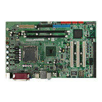
IEI Technology IMBA-9454B User Manual (192 pages)
ATX Motherboard, Dual VGA, Eight RS-232 Serial Ports
Brand:
IEI Technology
| Category:
Motherboard
| Size: 7.31 MB
Table of Contents
User Manual
1
Packing List
4
Table of Contents
5
1 Introduction
17
Features
18
Introduction
18
Overview
18
Figure 1-1: Overview
19
Peripheral Connectors and Jumpers
19
Technical Specifications
20
Table 1-1: Technical Specifications
22
2 Detailed Specifications
23
Dimensions
24
Figure 2-2: External Interface Panel Dimensions (MM)
24
Figure 2-3: Data Flow Block Diagram
25
Figure 2-4: CPU & Northbridge
26
Audio
27
Figure 2-5: Southbridge
27
IDE Interface
27
Intel® ICH7 Southbridge Chipset
27
PCI Interface
27
Real Time Clock
27
Pcie Bu Component
28
Pcie Bus Components
28
Pcie Mini Card Slot
28
Pcie X1 Expansion Slot
28
Realtek Pcie 8111CP Gbe Controller
28
SATA Controller
28
USB Controller
28
BIOS Chipset
29
Lpc Bus Components
29
Pci Bus Components
29
PCI Expansion Card Slot
29
Serial Port Chips
29
Enhanced Hardware Monitor
30
Environmental and Power Specifications
30
Fan Speed Controller
30
Keyboard and Mouse Controller
30
Parallel Port
30
Super I/O
30
System Monitoring
30
Operating Temperature and Temperature Control
31
Power Consumption
31
Figure 2-1: IMBA-9454B Dimensions (MM)
24
Compatible Processors
26
Intel® 945G Northbridge Chipset
26
Memory
26
Vga
26
Overview
24
Data Flow
25
Table 2-1: Power Consumption
32
3 Unpacking
33
Anti-Static Precautions
34
Unpacking
34
Unpacking Precautions
34
Unpacking Checklist
35
Package Contents
35
Optional Components
36
Table 3-1: Package List Contents
36
Table 3-2: Optional Components
37
4 Connector Pinouts
38
Figure 4-1: Connector and Jumper Locations
39
Table 4-1: Peripheral Interface Connectors
40
Table 4-2: External Peripheral Interface Panel Connectors
41
ATX Power Supply Connector (24-Pins)
42
Internal Peripheral Connectors
41
ATX Power Supply Connector (4-Pins)
41
Peripheral Interface Connectors
39
Layout
39
External Peripheral Interface Panel Connectors
40
Figure 4-2: ATX Power Supply Connector (4-Pins) Location
41
Table 4-3: ATX Power Supply Connector (4-Pins) Pinouts
42
Figure 4-3: ATX Power Connector Location
42
Fan Connectors
43
Figure 4-4: Fan Connectors Locations
43
Figure 4-16: USB Connector Pinout Locations
54
Figure 4-17: IMBA-9454B External Interface Connectors
55
Figure 4-18: PS/2 Pinouts
55
Figure 4-19: Parallel Port Connector Pinout Locations
56
Table 4-13: PS/2 Connector Pinouts
56
Ethernet Connector
57
Figure 4-20: Ethernet Connector Pinout Locations
57
Table 4-14: Parallel Port Connector Pinouts
57
Audio Connectors
58
Figure 4-21: Ethernet Connector
58
Table 4-15: Ethernet Connector Pinouts
58
Table 4-16: Ethernet Connector Leds
58
Table 4-17: USB Connector Pinouts
59
USB Connectors
59
VGA Connector
60
Table 4-4: ATX Power Connector Pinouts
43
Parallel Port Connector
56
Figure 4-5: FDC Connector Location
44
Floppy Disk Connector
44
Front Panel Connectors
44
Table 4-5: Fan Connectors Pinouts
44
Figure 4-6: Multi-Panel Connector Location
45
IDE Connector
45
Table 4-6: Multi-Panel Connector Pinouts
45
Figure 4-7: IDE Device Connector Locations
46
Figure 4-8: Line out Connector Location
46
Line out Connector
46
Figure 4-9: Pcie Mini Card Slot Location
47
Pcie Mini Card Slot
47
Pcie X1 Slot
47
Table 4-7: Line out Connector Pinouts
47
Figure 4-10: Pcie X1 Expansion Card Slot
48
Figure 4-11: PCI Slot Location
48
PCI Slot
48
Figure 4-12: SATA Drive Connector Locations
49
SATA Drive Connectors
49
Table 4-8: SATA Drive Connector Pinouts
49
Figure 4-13: Serial Port Connector 1 Location
50
Serial Port Connector 1
50
Figure 4-14: Serial Port Connector 2 Location
51
Serial Port Connector 2
51
Table 4-9: Serial Port Connector 1 Pinouts
51
SPI Flash Connector
52
Table 4-10: Serial Port Connector 2 Pinouts
52
Figure 4-15: SPI Flash Connector
53
Table 4-11: SPI Flash Connector
53
USB Connectors (Internal)
53
External Peripheral Interface Connectors
54
Table 4-12: USB Port Connector Pinouts
54
Keyboard/Mouse Connector
55
Figure 4-22: Audio Connector
59
Figure 4-23: USB Connector Pinout Locations
59
Table 4-18: VGA Connector Pinouts
60
Figure 4-24: VGA Connector
60
5 Installation
61
Anti-Static Precautions
62
Installation Considerations
62
Installation Notices
63
Installation Checklist
63
Cpu Installation
65
LGA775 CPU Installation
65
Figure 5-1: Intel LGA775
66
Figure 5-2: Remove the CPU Socket Protective Shield
66
Table 5-7: COM2 Voltage Setting
76
Table 5-8: COM3 Ri/Voltage Selection
76
Table 5-10: COM4 Ri/Voltage Selection
77
Table 5-11: COM4 Voltage Setting
77
ATA Flat Cable Connection
78
Internal Peripheral Device Connections
78
Table 5-12: IEI Provided Cables
78
Dual RS-232 Cable Connection
79
Figure 5-9: IDE Cable Connection
79
FDD Cable Connection
80
Figure 5-10: Dual RS-232 Cable Installation
80
Figure 5-11: FDD Cable Connection
81
Four Serial Port Connector
81
Figure 5-12: Four Serial Port Connector
82
Figure 5-13: Serial Device Connector
82
Pcie Mini Card Installation
82
Figure 5-14: Pcie Mini Card Installation
83
SATA Drive Connection
83
Figure 5-15: SATA Drive Cable Connection
84
Figure 5-16: SATA Power Drive Connection
84
External Peripheral Interface Connection
85
PS/2 Keyboard/Mouse Connection
85
Figure 5-17: PS/2 Keyboard/Mouse Connector
86
Figure 5-18: Parallel Port
86
Parallel Device Connection
86
Ethernet Connection
87
Figure 5-19: RJ-45 Ethernet Connector
87
USB Connection
87
Audio Connection
88
Figure 5-20: USB Connector
88
VGA Monitor Connection
89
Figure 5-3: Open the CPU Socket Load Plate
67
Figure 5-4: Insert the LGA775 CPU
68
Figure 5-5: IEI Cooling Kit
69
DIMM Installation
70
Figure 5-6: Securing the Heat Sink to the PCB Board
70
Figure 5-8: Jumper Locations
73
Table 5-1: Jumpers
73
Clear CMOS Jumper
74
Table 5-2: CF Master/Slave Selection Settings
74
Table 5-3: Clear CMOS Jumper Settings
74
COM1 Pin-9 Setup
75
COM2 Pin-9 Setup
75
Figure 5-7: Installing a DIMM
71
Jumper Settings
72
AT/ATX Power Selection
73
Table 5-6: COM2 Ri/Voltage Selection
75
Table 5-9: COM3 Voltage Setting
76
Chassis Installation
77
Table 5-4: COM1 Ri/Voltage Selection
75
Table 5-5: COM1 Voltage Setting
75
COM3 Pin-9 Setup
76
COM4 Pin-9 Setup
76
LGA775 Cooling Kit Installation
68
Figure 5-21: Audio Connectors
89
Figure 5-22: VGA Connector
89
6 Bios Setup
91
Introduction
92
Starting Setup
92
Using Setup
92
Getting Help
93
Unable to Reboot after Configuration Changes
93
BIOS Menu Bar
93
Table 6-1: BIOS Navigation Keys
93
BIOS Menu 1: Main
94
Advanced
95
Main
94
BIOS Menu 2: Advanced
96
CPU Configuration
97
BIOS Menu 3: CPU Configuration
97
IDE Configuration
98
BIOS Menu 4: IDE Configuration
98
IDE Master, IDE Slave
100
BIOS Menu 5: IDE Master and IDE Slave Configuration
100
Floppy Configuration
105
BIOS Menu 6: Floppy Configuration
105
Super IO Configuration
106
BIOS Menu 7: Super IO Configuration
106
Hardware Health Configuration
111
BIOS Menu 8: Hardware Health Configuration
111
Power Configuration
114
BIOS Menu 9: ACPI Configuration
114
General ACPI Configuration
115
BIOS Menu 10: General ACPI Configuration
115
APM Configuration
116
BIOS Menu 11: Advanced Power Management Configuration
116
Remote Access Configuration
118
BIOS Menu 12: Remote Access Configuration [Advanced]
118
USB Configuration
121
BIOS Menu 13: USB Configuration
121
USB Mass Storage Device Configuration
123
BIOS Menu 14: USB Mass Storage Device Configuration
123
Pci/Pnp
124
BIOS Menu 15: Pci/Pnp Configuration
124
Boot
126
BIOS Menu 16: Boot
126
Boot Settings Configuration
127
BIOS Menu 17: Boot Settings Configuration
127
Boot Device Priority
129
BIOS Menu 18: Boot Device Priority Settings
129
Hard Disk Drives
130
BIOS Menu 19: Hard Disk Drives
130
Removable Drives
131
BIOS Menu 20: Removable Drives
131
CD/DVD Drives
132
Security
132
BIOS Menu 21: CD/DVD Drives
132
BIOS Menu 22: Security
133
Chipset
134
BIOS Menu 23: Chipset
134
Northbridge Configuration
136
BIOS Menu 24: Northbridge Chipset Configuration
136
Exit
138
BIOS Menu 25:Exit
138
7 Driver Installation
140
Available Software Drivers
141
Driver CD Auto-Run
141
Figure 7-2: Available Drivers
142
Figure 7-1: Introduction Screen
142
Chipset Driver
143
Figure 7-3: Chipset Driver Installation Program
143
Figure 7-4: Chipset Driver Installation Welcome Screen
144
Figure 7-5: Chipset Driver License Agreement
144
Figure 7-6: Chipset Driver Installation
145
Figure 7-7: Chipset Driver Installation Complete
146
Vga Driver
146
Figure 7-9: VGA Driver Version Information
147
Figure 7-8: Select the Operating System
147
Figure 7-10: VGA Driver File Extraction
148
Figure 7-12: VGA Driver License Agreement
149
Figure 7-13: VGA Driver Readme File
149
Figure 7-16: LAN Driver Directory
151
Figure 7-18: LAN Driver Installation Ready
152
Figure 7-17: LAN Driver Welcome
152
Audio Driver
153
BIOS Setup
153
Driver Installation
153
Figure 7-11: VGA Driver Welcome Screen
148
Figure 7-14: VGA Driver Installing
150
Figure 7-15: Intel® Graphics Media Accelerator Installation Complete
150
Lan Driver
151
Figure 7-19: Device Manager List
153
Figure 7-20: Audio Driver Directory
154
Figure 7-21: Audio Driver Welcome Screen
154
Figure 7-22: Audio Driver Software Configuration
155
Figure 7-23: Audio Driver Digital Signature
155
Figure 7-24: Restart the Computer
156
ABIOS Options
157
B Terminology
161
C Digital I/O Interface
165
Introduction
166
Dio Connector Pinouts
166
C.1 I Ntroduction
166
C.2 Dio C Onnector P Inouts
166
Assembly Language Samples
167
C.3 a Ssembly L Anguage S Amples
167
Enable the DIO Input Function
167
Enable the DIO Output Function
167
D Watchdog Timer
168
E Address Mapping
171
Direct Memory Access (Dma)
172
Input/Output (IO)
172
E.1 D Irect M Emory a Ccess (Dma)
172
E.2 I Nput /O Utput (Io)
172
Interrupt Request (Irq)
174
E.3 I Nterrupt R Equest (Irq)
174
Memory
175
E.4 Memory
175
F Compatibility
176
Compatible Operating Systems
177
Compatible Processors
177
F.1 C Ompatible O Perating S Ystems
177
Compatible Memory Modules
178
G Hazardous Materials Disclosure
179
Hazardous Materials Disclosure Table for IPB Products Certified as Rohs Compliant under 2002/95/EC Without Mercury
180
HAC'97 Audio Codec
183
Introduction
184
Accessing the AC'97 CODEC
184
Driver Installation
184
H.1 I Ntroduction
184
Sound Effect Configuration
185
Accessing the Sound Effects Manager
185
Sound Effect Manager Configuration Options
186
Advertisement
Advertisement
Related Products
IEI Technology IMBA-9454G
IEI Technology IMBA-9454ISA
IEI Technology IMBA-9454
IEI Technology IMBA-9654
IEI Technology IMBA-9454B-R11
IEI Technology IMBA-G412ISA
IEI Technology IMBA-H610
IEI Technology imba-30104
IEI Technology IMBA-BDE-1518
IEI Technology IMBA-BDE
IEI Technology Categories
Motherboard
Touch Panel
Computer Hardware
Single board computers
Desktop
More IEI Technology Manuals
Login
Sign In
OR
Sign in with Facebook
Sign in with Google
Upload manual
Upload from disk
Upload from URL