HP ProCurve Series 6600 Installation And Getting Started Manual
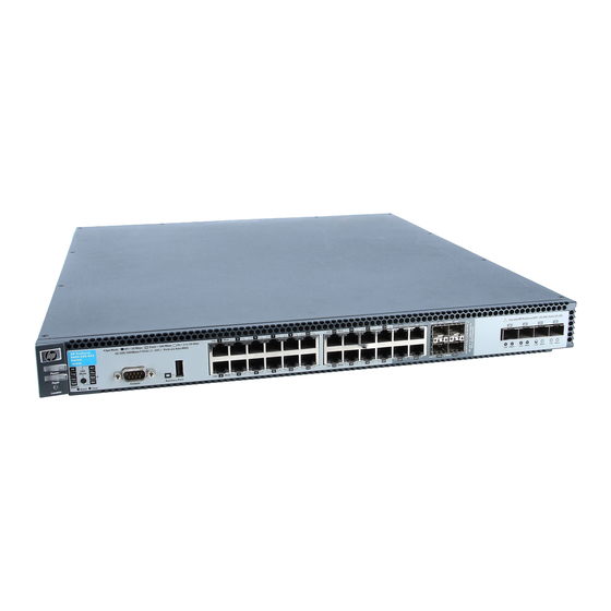
Procurve 6600 series switches
Hide thumbs
Also See for HP ProCurve Series 6600:
- Security configuration manual (559 pages) ,
- Command reference manual (286 pages) ,
- Configuration manual (236 pages)

Related Manuals for HP HP ProCurve Series 6600


Summary of Contents for HP HP ProCurve Series 6600
- Page 1 HP ProCurve Series 6600 Switches www.procurve.com Installation and Getting Started Guide...
-
Page 3: Procurve Series 6600 Switches
ProCurve Series 6600 Switches Installation and Getting Started Guide... -
Page 4: Publication Number
Nothing herein should be construed as constituting an additional warranty. HP shall not be liable for technical or editorial errors or (J9263A) omissions contained herein. (J9264A) -
Page 5: Table Of Contents
1. Prepare the Installation Site ....... . 2-5 2. Verify the Switch Passes Self Test ......2-5 LED Behavior: . - Page 6 Console Cable Pinouts ........2-21 Checking the Switch LEDs ....... . 5-9...
- Page 7 Downloading New Switch Software ......5-12 HP Customer Support Services ........5-12 Before Calling Support .
- Page 8 C Safety and EMC Regulatory Statements Safety Information ..........C-1 Informations concernant la sécurité...
-
Page 9: Introducing The Switch
Introducing the Switch Introducing the Switch The HP ProCurve Series 6600 Switches are top-of-rack data center switches that support advanced Layer three switching, and have reversible front-to- back airflow, and two hot-swappable power supplies. These switches can be used to build high-speed switched networks between servers in the data center. - Page 10 10/100/1000Base-T RJ-45 or mini- GBIC (Small Form-Factor Pluggable (SFP)) ports. The 6600-24G-4XG Switch has the same ports as the Switch 6600-24G plus it also has 4 SFP+ slots for 10-GbE connectivity. The specification for SFP+ defines the physical and electrical characteristics of this form-factor (size and shape).
- Page 11 These switches can directly connect servers to other servers or backbone LANs to provide dedicated bandwidth to those devices, and can build a switched network infrastructure by connecting the switch to hubs, other switches, or routers. In addition, the Series 6600 Switches offer full network management capabilities.
-
Page 12: Front Of The Switch
Fault, and Locator LEDs Console port Port LED Mode select button and indicator LEDs Reset and Clear buttons Figure 1-1. ProCurve 6600-24G Switch PS, Tmp, Fan, and Test Power, Status LEDs Fault, and Locator LEDs Console port Port LED Mode select... -
Page 13: Network Ports
RJ-45 connector is disabled and cannot be used. If the mini-GBIC is removed, the associated RJ-45 port is automatically re-enabled. ■ On the 6600-24XG Switch there are 24 SFP+ 10-GbE ports. SFP+ ports only support 10 Gbps operation; 1 Gbps mini-GBICs are not supported in any SFP+ port. -
Page 14: Leds
Blinking A fault has occurred on one of the power supplies. The PS Status LED, Fault LED, orange and on the back of the switch the failed power supply LED (PS1 or PS2) will all blink simultaneously. On green Switch temperature is normal. - Page 15 The switch self test and initialization are in progress after the switch has been power cycled or reset. The switch is not operational until this LED goes off. The Self Test LED also comes on briefly when you “hot swap” a mini-GBIC into the switch;...
-
Page 16: Led Power Save Mode
The Blinking behavior is an on/off cycle once every 0.8 seconds, approximately. LED Power Save Mode The HP ProCurve 6600-24XG Switch (J9265A) has the ability to turn off defined groups of ports to save power through the use of a CLI command, “savepower”. -
Page 17: Reset Button
The Usr Mode LED indicates the port is displaying customer-specified ■ information. Reset Button This button is for: Resetting the switch - When the switch is powered on. This action clears ■ any temporary error conditions that may have occurred and executes the switch self test. ■... -
Page 18: Clear Button
■ Console Port This port is used to connect a console to the switch either by using the RJ-45 to DB9 cable or the DB9 to DB9 serial cable supplied with the switch. The Series 6600-24G and 6600-24G-4XG Switches use the DB9 to DB9 serial cable and the 6600-24XG Switch uses the RJ-45 to DB cable. -
Page 19: Back Of The Switch
Power supply and Locator LEDs Power supply AC power connector Figure 1-6. HP ProCurve Series 6600 Switches. The backs of all these switches are the same. Power Connector The Series 6600 Switches do not have a power switch; they are powered on when connected to an active AC power source. - Page 20 MDI; if the switch detects that an end-node device is connected to the port, it configures the port as MDI-X.
-
Page 21: Installing The Switch
This chapter shows how to install the switch. C a u t i o n If the switch is to be shipped in a rack, be sure to use only an HP 10K rack. Mount the switch using rail mounting kit, (5070-6532). The switch warranty may be voided. - Page 22 Installing the Switch Included Parts ■ Power cord, one of the following: Australia/New Zealand China Continental Europe Denmark Japan Switzerland United Kingdom/Hong Kong/Singapore United States/Canada/Mexico South Africa India Argentina Thailand Brazil Chile Taiwan Israel J a p a n P o w e r...
-
Page 23: Installation Precautions
C a u t i o n s The Series 6600 Switches should be mounted with the optional Rail ■ Mounting Kit (5070-6532) in an HP 10000 (HP 10K) rack or any 4 post racking solution. ■ Ensure the power source circuits are properly grounded, then use the power cord supplied with the switch to connect it to the power source. -
Page 24: Installation Procedures
Summary Prepare the installation site ment is properly prepared, including having the correct network cabling ready to connect to the switch and having an appropriate location for the switch. See Verify the switch passes self test power source and observe that the LEDs on the switch’s front panel indicate correct switch operation. -
Page 25: Prepare The Installation Site
PC to the switch’s console port. At this point, the switch is fully installed. See the rest of this chapter if you need more detailed information on any of these installation steps. - Page 26 If your installation requires a different power cord than the one supplied with the switch, be sure to use a power cord displaying the mark of the safety agency that defines the regulations for power cords in your country. The mark is your assurance that the power cord can be used safely with the switch.
-
Page 27: Led Behavior
The Power and Fan Status LEDs remain on. • • The Fault and Test LEDs go off. • The port LEDs on the front of the switch go into their normal operational mode: Installing the Switch Installation Procedures Switch port LEDs... -
Page 28: Optional) Reversing The Air Flow
Installing the Switch Installation Procedures – – If the LED display is different than what is described above, especially if the Fault and Test LEDs stay on for more than 60 seconds or they start blinking, the self test has not completed correctly. Refer to chapter 4, “Troubleshooting”... - Page 29 Take care to align the sensing pin between the two sensors and replace the 4 retaining screws. Sensors Sensing pin Replace the fan tray assembly into the switch. Tighten the retaining screws. Installing the Switch Installation Procedures Rotating fan...
-
Page 30: Mount The Switch
2-5. Flush mounting in a two post rack is not supported. Or with the optional Rail Mounting Kit (5070-6532) in an HP 10000 (HP 10K) rack or any 4 post racking solution, see figures 2-6 through 2-10. - Page 31 Figure 2-5. Mounting in a two post rack using the balanced option. Use a #1 Phillips (cross-head) screwdriver and attach the mounting brackets to the switch with the included 8-mm M4 screws. Remember to use the correct accessory kit for your switch, see Figure 2-6.
- Page 32 Attach the holding brackets. Ensure the holes of the brackets and the screws are aligned to the bottom of the switch. Figure 2-7. Installing the rail mounting holding brackets Install the rails. Figure 2-8. Mounting rails in a four-post HP 10K rack 2-12...
- Page 33 12-24 screws holding the brackets to the rack. Figure 2-10. Mounting in a rack C a u t i o n Make sure the air flow is not restricted in the front or back of the switch. See Figure 2-1 on page 2-4 for the air flow direction.
-
Page 34: Connect The Switch To A Power Source
Installing the Switch Installation Procedures 5. Connect the Switch to a Power Source Plug the included power cord into the switch’s power connector and into a nearby AC power source. Re-check the LEDs during self test. See “LED Behavior” on Securing the power cord 1.Connect the power cord to the power supply. -
Page 35: Optional) Install Or Remove Mini-Gbics Or Sfps
6. (Optional) Install or Remove mini-GBICs or SFPs You can install or remove a mini-GBIC from a mini-GBIC slot without having to power off the switch. Use only ProCurve transceiver accessories. N o t e s The mini-GBIC slots are shared with the four 10/100/1000Base-T RJ-45 ■... -
Page 36: Installing The Mini-Gbics Or Sfp+ Transceivers
C a u t i o n Use only supported genuine HP ProCurve transceiver accessories with your switch. Non-ProCurve transceiver accessories are not supported, and their use may result in product malfunction. Should you require additional ProCurve transceiver accessories, contact your ProCurve Networking Sales and Service Office or authorized dealer. -
Page 37: Sfp And Sfp+ Transceivers Plug-In, Fault And Alert Behaviors
LED has turned off. For a faulty or non-ProCurve Transceiver: ■ The switch Fault LED and port Link LED for the affected port would be slow flashed for situations that cannot be fixed by the customer. For working but unsupported transceiver including:... -
Page 38: Connect The Network Cables
(you can see it move outward slightly), and then pull it from the slot. To remove the mini-GBICs that have the wire bail, lower the bail until it is approximately horizontal, and then using the bail, pull the mini-GBIC from the slot. -
Page 39: Optional) Connect A Console To The Switch
Out-of-band: The switch comes with a cable for connecting a PC or VT- ■ 100 terminal, to be used as a console, directly to the switch. You can use the console port only for out-of-band management. It cannot be used for a Telnet connection. -
Page 40: Terminal Configuration
“Function, Arrow, and Ctrl Keys act as” parameter If you want to operate the console using a different configuration, make sure you change the settings on both the terminal and on the switch so they are compatible. Change the switch settings first, save your changes, then change the terminal settings, then reboot the switch and reestablish the console session. -
Page 41: Console Cable Pinouts
(CLI) prompt, for example: ProCurve Switch 6600-24G# If you want to continue with console management of the switch at this time, see chapter 3, “Getting Started With Switch Configuration” configuration steps. For more detailed information, refer to the Management and Configuration Guide, which is on the ProCurve Web site at www.procurve.com/manuals. -
Page 42: Sample Network Topology
Installing the Switch Sample Network Topology Table 2-18. Mapping of RJ-45 to DB-9 RJ-45 (Signal reference from Chassis TX_Debug RX_Debug Sample Network Topology An industry standard building block approach requires that applications can be adapted to a common server environment. Virtualization of these resources allows for improved scaling, flexibility, and efficient use of resources, while delivering seamless interoperability. - Page 43 In such a model, server/access layer network infrastructure can be completely standardized and continuously deployed without regard to application requirements. Gigabit fiber cable ProCurve Switch 6600 Servers Servers Figure 2-19. Example topology Installing the Switch Sample Network Topology Gigabit fiber cable...
-
Page 45: Getting Started With Switch Configuration
Recommended Minimal Configuration Getting Started With Switch Configuration This chapter is a guide for using the console Switch Setup screen to quickly assign an IP (Internet Protocol) address and subnet mask to the switch, set a Manager password, and, optionally, configure other basic features. -
Page 46: Using The Console Setup Screen
Using the Console Setup Screen N o t e By default, the switch is configured to acquire an IP address configuration from a DHCP or Bootp server. To use DHCP/Bootp instead of the manual method described in this chapter, see “DHCP/Bootp Operation” in the Management and Configuration Guide, which is on the ProCurve Web site at www.procurve.com/manuals. - Page 47 Recommended; If you set IP Config to Manual, then enter an IP address Note: The IP address and subnet mask assigned for the switch must be compatible with the IP addressing used in your network. For more information on IP addressing, see the Management and Configuration Guide, which is on the ProCurve Web site at www.procurve.com/manuals.
-
Page 48: Where To Go From Here
The above procedure configures your switch with a Manager password, IP address, and subnet mask. As a result, with the proper network connections, you can now manage the switch from a PC equipped with Telnet, a web browser interface, or from an SNMP-based network management station using a tool such as ProCurve Manager. -
Page 49: Using The Ip Address For Remote Switch Management
Management The switch’s IP address can be used to manage the switch from any PC that is on the same subnet as the switch. Either a Telnet session or a standard web browser can be used to manage the switch. - Page 50 An extensive help system is also available for the web browser interface. To access the help system though, the subnet on which the switch is installed must have access to the internet, or ProCurve Manager needs to be installed on a network management station that is on the subnet.
-
Page 51: Replacing Components
C a u t i o n The HP ProCurve Series 6600 Switch and its components are sensitive to static discharge. Use an antistatic wrist strap and observe all static precautions when replacing components. - Page 52 Replacing Components Replacing the fan tray assembly C a u t i o n If the fan assembly is replaced with the switch powered on, you will have approximately three minutes before the switch overheats. To replace a fan tray assembly: Unscrew the retaining screws.
-
Page 53: Replacing The Battery
Replacing the Battery The battery is used to keep time for the internal switch clock. There is not LED indicator for when the battery no longer has sufficient power. The only indication will be the internal clock will not keep the correct time. The battery is not hot swappable. - Page 54 Insert a new battery with the lettering and the plus “+” sign facing up. Be sure to replace with the same type of battery. Reinstall the top of the switch. Reinstall and tighten all the screws securing the top. Reconnect the power cable(s).
-
Page 55: Replacing The Power Supplies
Replacing the Power Supplies If your HP ProCurve Series 6600 Switch is configured with redundant power supplies, the switch will not suffer any loss of traffic or performance if a power supply fails. Replace the failed component as soon as possible. The PS (Power Supply) LED will blink simultaneously with the switch Fault LED indicating a power supply has failed. -
Page 57: Troubleshooting
Connecting to devices that have a fixed full-duplex configuration. The RJ-45 ports are configured as “Auto”. That is, when connecting to attached devices, the switch will operate in one of two ways to determine the link speed and the communication mode (half duplex or full duplex): •... - Page 58 Because the switch behaves in this way (in compliance with the IEEE 802.3 standard), if a device connected to the switch has a fixed configuration at full duplex, the device will not connect correctly to the switch. The result will be high error rates and very inefficient communications between the switch and the device.
- Page 59 ■ Check the port configuration. A port on your switch may not be operating as you expect because it has been put into a “blocking” state by Spanning Tree, GVRP (automatic VLANs), or LACP (automatic trunking). (Note that the normal operation of the Spanning Tree, GVRP, and LACP features may put the port in a blocking state.) Or, the port just may have...
-
Page 60: Diagnosing With The Leds
Troubleshooting Diagnosing with the LEDs Diagnosing with the LEDs Table 5-1 shows LED patterns on the switch and the switch modules that indicate problem conditions. Check in the table for the LED pattern you see on your switch. Refer to the corresponding diagnostic tip on the next few pages. -
Page 61: Diagnostic Tips
Try power cycling the switch. If the fault indication reoccurs, the switch may have failed. hardware failure Call your ProCurve authorized LAN dealer, or use the electronic support services from HP has occurred. All to get assistance. See the Customer Support/Warranty booklet for more information. - Page 62 – For twisted-pair connections to the fixed 10/100 or 10/100/1000 ports, if the port is configured to “Auto” (auto negotiate), either straight-through or crossover cables can be used because of the switch’s “HP Auto-MDIX” feature and the Auto MDI/ MDI-X feature of the 10/100/1000-T port.
- Page 63 Use the switch console to see if the port is part of a dynamic trunk (through the LACP improperly feature) or to see if Spanning Tree is enabled on the switch, and to see if the port may configured, or have been put into a “blocking”...
-
Page 64: Proactive Networking
Troubleshooting Proactive Networking Proactive Networking The HP ProCurve Series 6600 Switches have built-in management capabilities that proactively help you manage your network including: ■ finding and helping you fix the most common network error conditions (for example, faulty network cabling, and non-standard network topolo-... -
Page 65: Hardware Diagnostic Tests
Checking the Switch LEDs The self test passes if the Fault and Self Test LEDs on the front of the switch go off after approximately 50 seconds. If these LEDs stay on longer than 60 seconds or begin Blinking, there may be a problem with the switch. -
Page 66: Testing Twisted-Pair Cabling
LAN adapters between which you can run a link-level test or Ping test through the switch, you can use this test to verify that the entire communication path between the two PCs is functioning correctly. See your LAN adapter documentation for more information on running a link test or Ping test. -
Page 67: Restoring The Factory Default Configuration
(usually disabling them) may result in network connectivity issues. If the switch has a valid configuration, and you are restoring the factory default settings for a reason other than configuration problems, you should save the switch configuration prior to performing the factory default reset. -
Page 68: Downloading New Switch Software
24 hours a day, seven days a week through the use of a number of automated electronic services. See the Customer Support/Warranty booklet that came with your switch for information on how to use these services to get technical support. The ProCurve Web site at up-to-date support information. -
Page 69: Specifications
Electrical AC voltage: 100-127/200-240 volts Maximum current: 1.8A/0.9A 50/60 Hz Frequency range: The switch automatically adjusts to any voltage between 100-127 and 200-240 volts and either 50 or 60 Hz. Environmental Temperature: Relative humidity: (non-condensing) Maximum altitude: HP ProCurve 6600-24G-4XG... -
Page 70: Acoustic
Specifications Acoustic HP ProCurve Switch 6600-24G (J9263A) Geraeuschemission LpA=62.3 dB am fiktiven Arbeitsplatz nach DIN 45635 T.19 Noise Emission LpA=49.3 dB at virtual workspace according to DIN 45635 T.19 HP ProCurve Switch 6600-28G-4XG (J9264A) Geraeuschemission LpA=59.5 dB am fiktiven Arbeitsplatz nach DIN 45635 T.19... - Page 71 Table A-1. Technology standards and safety compliance Technology Compatible with these IEEE standards 10/100/1000-T IEEE 802.3 10BASE-T, IEEE 802.3u 100BASE-TX, IEEE 802.3ab 1000BASE-T 100-FX IEEE 802.3u 100BASE-FX 100-BX IEEE 802.3ah 100BASE-BX10 1000-SX IEEE 802.3z 1000BASE-SX 1000-LX IEEE 802.3z 1000BASE-LX 1000-LH (not an IEEE standard) 1000-BX IEEE 802.3ah 1000BASE-BX10...
-
Page 73: B Cabling And Technology Information
Cabling and Technology Information This appendix includes network cable information for cables that should be used with the Switch 6600, including minimum pin-out information and specifications for twisted-pair cables. N o t e Incorrectly wired cabling is the most common cause of problems for LAN communications. - Page 74 Equal-Level Far-End Crosstalk (ELFEXT) and Return Loss. When testing your cabling, be sure to include the patch cables that connect the switch and other end devices to the patch panels on your site. The patch cables are frequently overlooked when testing cable and they must also...
-
Page 75: Technology Distance Specifications
Technology distance specifications Table B-2. Technology Supported cable type 100-FX multimode fiber 100-BX single mode fiber 1000-T twisted-pair copper 1000-SX multimode fiber 1000-LX multimode fiber single mode fiber 1000-LH single mode fiber 1000-BX single mode fiber 10-Gig Direct Attach twinaxial copper 10-Gig SR multimode fiber 10-Gig LRM... -
Page 76: Mode Conditioning Patch Cord
CRC or FCS errors, you may need to install one of these patch cords between the fiber-optic port in your switch and your multimode fiber-optic network cabling, at both ends of the network link. -
Page 77: Installing The Patch Cord
Installing the Patch Cord As shown in the illustration below, connect the patch cord to the ProCurve transceiver with the section of single mode fiber plugged in to the Tx (transmit) port. Then, connect the other end of the patch cord to your network cabling patch panel, or directly to the network multimode fiber. -
Page 78: Twisted-Pair Cable/Connector Pin-Outs
-- you no longer have to use crossover cables, although crossover cables can also be used for any of the connections. If you connect a Switch 6600 twisted-pair port to another switch or hub, which typically have MDI-X ports, the Switch 6600 port automatically operates as an MDI port. -
Page 79: Straight-Through Twisted-Pair Cable For 10 Mbps Or 100 Mbps Network Connections
Straight-Through Twisted-Pair Cable for 10 Mbps or 100 Mbps Network Connections Because of the HP Auto-MDIX operation of the 10/100 ports on the switch, for all network connections, to PCs, servers or other end nodes, or to hubs or other switches, you can use straight-through cables. -
Page 80: Crossover Twisted-Pair Cable For 10 Mbps Or 100 Mbps Network Connection
Crossover Twisted-Pair Cable for 10 Mbps or 100 Mbps Network Connection The HP Auto-MDIX operation of the 10/100 ports on the switch also allows you to use crossover cables for all network connections, to PCs, servers or other end nodes, or to hubs or other switches. -
Page 81: Straight-Through Twisted-Pair Cable For 1000 Mbps Network Connections
Straight-Through Twisted-Pair Cable for 1000 Mbps Network Connections 1000Base-T connections require that all four pairs or wires be connected. Cable Diagram N o t e Pins 1 and 2 on connector “A” must be wired as a twisted pair to pins 1 and 2 on connector “B”. -
Page 83: C Safety And Emc Regulatory Statements
These products do not have a power switch; they are powered on when the power cord is plugged in. Documentation reference symbol. If the product is marked with this symbol, refer to the product documentation to get more information about the product. -
Page 84: Informations Concernant La Sécurité
Safety and EMC Regulatory Statements Informations concernant la sécurité Informations concernant la sécurité WARNING Caution Cet appareil est un produit de classe I et possède une borne de mise à la terre. La source d'alimentation principale doit être munie d'une prise de terre de sécurité installée aux bornes du câblage d'entrée, sur le cordon d'alimentation ou le cordon de raccordement fourni avec le produit. -
Page 85: Hinweise Zur Sicherheit
Hinweise zur Sicherheit Symbol für Dokumentationsverweis. Wenn das Produkt mit diesem Symbol markiert ist, schlagen Sie bitte in der Produktdokumentation nach, um mehr Informationen über das Produkt zu erhalten. WARNING Eine WARNING in der Dokumentation symbolisiert eine Gefahr, die Verletzungen oder sogar Todesfälle verursachen kann. Caution Caution in der Dokumentation symbolisiert eine Gefahr, die dis Gerät beschädigen kann. -
Page 86: Considerazioni Sulla Sicurezza
Safety and EMC Regulatory Statements Considerazioni sulla sicurezza Considerazioni sulla sicurezza WARNING Caution Questo prodotto è omologato nella classe di sicurezza I ed ha un terminale protettivo di collegamento a terra. Dev'essere installato un collegamento a terra di sicurezza, non interrompibile che vada dalla fonte d'alimentazione principale ai terminali d'entrata, al cavo d'alimentazione oppure al set cavo d'alimentazione fornito con il prodotto. -
Page 87: Consideraciones Sobre Seguridad
Consideraciones sobre seguridad Símbolo de referencia a la documentación. Si el producto va marcado con este símbolo, consultar la documentación del producto a fin de obtener mayor información sobre el producto. WARNING Una WARNING en la documentación señala un riesgo que podría resultar en lesiones o la muerte. -
Page 88: Safety Information (Japan
Safety and EMC Regulatory Statements Safety Information (Japan) Safety Information (Japan) J a p a n P o w e r C o r d W a r n i n g... -
Page 89: Safety Information (China
Safety and EMC Regulatory Statements Safety Information (China) Safety Information (China) -
Page 90: Australia/New Zealand
Safety and EMC Regulatory Statements EMC Regulatory Statements EMC Regulatory Statements U.S.A. FCC Class A This equipment has been tested and found to comply with the limits for a Class A digital device, pursuant to Part 15 of the FCC Rules. These limits are designed to provide reasonable protection against interference when the equipment is operated in a commercial environment. -
Page 91: European Community
Number is the main product identifier in the regulatory documentation and test reports, this number should not be confused with the marketing name or the product numbers. 2) This product was tested with HP branded products only. Roseville, 16-September-2008 Local contact for regulatory information: EMEA: Hewlett-Packard GmbH, HQ-TRE, Herrenberger Straße 140, D-71034 Böblingen, Germany... -
Page 93: D Recycle Statements
Recycle Statements Waste Electrical and Electronic Equipment (WEEE) Statements Disposal of Waste Equipment by Users in Private Household in the European Union This symbol on the product or on its packaging indicates that this product must not be disposed of with your other household waste. - Page 94 Recycle Statements Waste Electrical and Electronic Equipment (WEEE) Statements Laitteiden hävittäminen kotitalouksissa Euroopan unionin alueella Jos tuotteessa tai sen pakkauksessa on tämä merkki, tuotetta ei saa hävittää kotitalousjätteiden mukana. Tällöin hävitettävä laite on toimitettava sähkölaitteiden ja elektronisten laitteiden kierrätyspisteeseen. Hävitettävien laitteiden erillinen käsittely ja kierrätys auttavat säästämään luonnonvaroja ja varmistamaan, että...
- Page 95 Smaltimento delle apparecchiature da parte di privati nel territorio dell'Unione Europea Questo simbolo presente sul prodotto o sulla sua confezione indica che il prodotto non può essere smaltito insieme ai rifiuti domestici. È responsabilità dell'utente smaltire le apparecchiature consegnan- dole presso un punto di raccolta designato al riciclo e allo smaltimento di apparecchiature elettriche ed elettroniche.
- Page 96 Para obter mais informações sobre locais que reciclam esse tipo de material, entre em contato com o escritório da HP em sua cidade, com o serviço de coleta de lixo ou com a loja em que o produto foi adquirido.
- Page 97 … B-3 AC power connector location on back of switch … 1-11 Act LED … 1-7, 1-9 auto MDI/MDI-X operation … B-7, B-9 HP Auto-MDIX feature … B-6 back of switch description … 1-11 power connector … 1-11 basic switch configuration IP address …...
- Page 98 LED view select button and LEDs … 1-8 Reset button … 1-9 full-duplex fixed configuration effects on network connections … 5-1 full-duplex operation of mini-GBICs … 2-15 hot swapping … 4-1 HP Auto-MDIX feature description … B-6 in-band … 3-1...
- Page 99 … 2-10 precautions … 2-3 network cables fiber-optic, specifications … B-3 HP Auto-MDIX feature … B-6 required types … 2-5 twisted-pair connector pin-outs … B-6 twisted-pair, wiring rules … B-6 network devices connecting to the switch …...
- Page 100 … 2-7 ports 10/100Base-TX, location on switch … 1-4 connecting to … 2-18 console … 2-19 HP Auto-MDIX feature … B-6 network connections … 2-18 power connector … 1-11 Power LED … 1-6 behavior during self test … 2-7 behaviors …...
- Page 101 … B-7, B-9 switch-to-computer connection … B-7, B-9 switch-to-switch or hub connection … B-8 testing … 5-10 twisted-pair ports HP Auto-MDIX feature … B-6 Usr LEDs … 1-7 Usr Mode LED … 1-9 voltage ranges … 1-11, 2-6 VT-100 terminal serial cable connection for …...
- Page 103 © Copyright 2009 Hewlett-Packard Development Company, L.P. January 2009 Manual Part Number 5992-4962 *5992-4962*...
Need help?
Do you have a question about the HP ProCurve Series 6600 and is the answer not in the manual?
Questions and answers