
Related Manuals for WTI APS-8M


Summary of Contents for WTI APS-8M
- Page 1 WTI Part No. 13202 Rev. C APS-8M Asynchronous Port Switch with Internal Modem Firmware Version 2.30 User's Guide...
-
Page 3: Warnings And Cautions
Warnings and Cautions: No Serviceable Parts Inside; Authorized Service Personnel Only Do not attempt to repair or service this device yourself. Internal components must be serviced by authorized personnel only. • Shock Hazard - Do Not Enter Nameplate Power Warning This device should only be operated with the type of power source indicated on the instrument nameplate. - Page 4 APS-8M User’s Guide Rack Mount Installation (Continued) 1. Enclosed Racks (Continued): The ambient within the rack may be greater than room ambient. Installation should be such that the amount of air flow required for safe operation is not compromised. The maximum temperature for the equipment in this environment is 45°C.
-
Page 5: Table Of Contents
Table of Contents Introduction ..........1-1 Unit Description . - Page 6 Restoring Saved Parameters ......9-2 10. Upgrading APS-8M Firmware ......10-1 11.
-
Page 7: Introduction
Configuration of the APS-8M is simple. A menuing system is used to select communications parameters, and enable or disable options. The APS-8M can easily adapt to the requirements of almost any data communications application. Password Protected Connection and Command Access The APS-8M provides two levels of user security;... - Page 8 APS-8M User’s Guide Modem Communication The APS-8M can be controlled by a local PC that communicates with the unit via cable, or controlled remotely via external modem. Hyperterminal (or another communications program) is used to send commands to connect ports or display status.
-
Page 9: Unit Description
Unit Description 2.1. Front Panel Figure 2.1: Instrument Front Panel ¬ CLEAR: Restarts the APS operating program without changing user-selected parameter settings or breaking port connections. ON: Lights when AC Power is applied. ® SET: Used to Initialize the APS to defaults specified by the SetUp Switches. -
Page 10: Back Panel
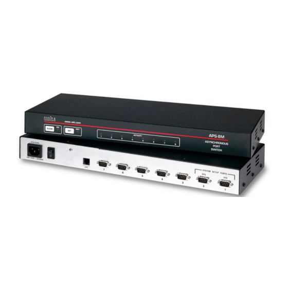
APS-8M User’s Guide 2.2. Back Panel Figure 2.2: Instrument Back Panel ¬ Power Cable Receptacle AC powered units only. DC units include a terminal block assembly as described in Section 4.1.2. Power Switch ® SetUp Switches: A bank of eight DIP switches, which set default communication parameters and other features as described in Section 4.2. -
Page 11: Getting Started
Modem Port, located on the APS-8M back panel. For more information, please refer to Section 4.4. and Appendix A. 3. Connect a PC to the APS-8M: Attach a standard null modem cable from your PC COM port to the Port 1 connector on the APS-8M back panel. - Page 12 6. Port Status Screen: Type /S and press [Enter] to display the Port Status Screen (Figure 3.2), which summarizes conditions at all APS-8M ports. The various fields of the Port Status Screen are explained further in Section 7.1. 7. Port Connection: The APS-8M can perform two different types of port connections;...
-
Page 13: The Port Status Screen
Type /S [Enter] to display the Port Status Screen. The "STATUS" column should now list Ports 2 and 3 as "Free". 8. Exit Command Mode: At the "APS>" command prompt, type /X and press [Enter]. The APS-8M will exit command mode. - Page 14 Port Connection / Disconnection examples described in Step 7 above. b) When you have finished communicating with the APS-8M unit, type /X and press [Enter] to exit command mode and terminate the modem connection to the unit.
-
Page 15: Hardware Installation
Hardware Installation 4.1. Connecting Power to the APS Unit The APS-8M is available in both AC and DC powered versions. When connecting power, proceed as follows: CAUTION: This device should only be operated with the type of power source indicated on the instrument nameplate. -
Page 16: Configure Setup Switches
4.2. Configure SetUp Switches The SetUp Switches are used to select default settings for the RS232 ports. The SetUp Switches are located on the APS-8M back panel, as shown in Figure 2.1. When the APS-8M is shipped from the factory, the SetUp Switches... -
Page 17: Default Baud Rate (Sw1, Sw2, Sw3)
RS232 Ports One through Seven. The default baud rate must match the rate that your control device (the PC that will be used to configure and control the unit) will use when communicating with the APS-8M. Notes: · If the control device will communicate via an external... -
Page 18: Default Handshake (Sw4, Sw5)
RTS/CTS (hardware), XON/XOFF, Both or None. Notes: · If the control device will communicate with the APS-8M via an external modem connected to one of the RS232 ports, select a default handshaking format that is compatible with the external modem. ·... -
Page 19: Default Response Message Format (Sw6)
Default Command Echo (Sw7) Switch Seven enables or disables the Command Echo. When enabled, characters sent to the APS-8M will be echoed back to the control device. Note that the /P command can also be used to selectively enable or disable the Command Echo at each individual port. -
Page 20: Initialize Unit To Default Settings
APS-8M User’s Guide 4.3. Initialize Unit to Default Settings If SetUp Switch settings are changed, new parameters will not take effect until the APS-8M is initialized. CAUTION: After initialization, the unit will revert to the parameters specified by the SetUp Switches, and command-selected parameters will be lost. -
Page 21: Configuration
Configuration 5.1. Access to the APS Command Mode When the APS-8M command mode is active, commands can be invoked to select parameters, and connect or disconnect ports. Note: · Command mode cannot be accessed from a Buffer Mode Port, Passive Mode Port, or any port that is currently connected to another APS-8M port. -
Page 22: System Setup Ports
The APS-8M's password directory allows you to define up to 32 different passwords. These passwords are not only used to protect access to the APS-8M unit, but are also used to determine the type of commands that each user will be allowed to invoke, and the ports that each user will be allowed to connect. -
Page 23: The System Parameters Menu
· If you wish to restrict users from changing APS-8M configuration parameters or connecting to restricted ports, you must define at least one password that permits access to Supervisor Mode as described in Section 5.4.1. -
Page 24: The System Parameters Menu (/F)
• 3. Dial Back Attempts: Sets the number of times that the APS-8M will attempt to call the dial back number when the Dial Back feature is properly configured and enabled. For more information on the Dial Back feature, please refer to Section 5.4.2. -
Page 25: The Password Directory
Figure 5.2: The Edit Password Directory Menu 5.4.1. The Password Directory APS-8M passwords are defined using the "Edit Password Directory" menu, which is accessed via the System Parameters menu (/F). In addition to assigning command level privileges to each password, the Edit Password Directory function also allows you to determine which ports each password will be allowed to access. -
Page 26: The Add Name/Password Menu (Defaults Shown)
• 3. Dial Back #: Defines the number that the APS-8M will dial when the Dial Back feature is enabled and the unit is contacted via modem. For more information on the Dial Back Mode, please refer to Section 5.4.2. -
Page 27: The Edit/Delete Name/Password Menu (Sample Values Shown)
Configuration EDIT/DELETE NAME/PASSWORD: 1. Name: test 2. Password: (defined) 3. Dial Back #: 5556789 4. Dial Back Mode: 5. Supervisor Mode: On 6. Port Access: 1, 2, 3, 4, 5, 6, 7, 8 7. Save Entry 8. Delete Entry Type: "<"<Enter> previous entry, ">"<Enter> next entry, <number><Enter>... -
Page 28: The Dial Back Function
If desired, users may also be required to re-enter the password after the APS-8M dials back. Note that a separate Dial Back Number can be defined for each password, and the feature may also be independently enabled for each password. - Page 29 3. Password on Dialback: When the modem at the Dial Back Number answers, the APS-8M will prompt the user to enter the password before allowing access to command mode. 4. Dial Back Attempts and Delays: If the modem does not...
-
Page 30: Port Configuration
Passwords are case sensitive. When defining passwords, note the exact text, including the case of each character. · If you are configuring the APS-8M unit via modem, communication parameters will not be changed until after you exit from command mode and disconnect from the APS-8M unit. -
Page 31: Port Modes
Any-to-Any Mode, but the Modem Mode also allows definition of a Hang-Up String, Reset String, and Initialization String. Any APS-8M RS232 port can be configured for Modem Mode, and Port 8 (the External Modem port) is always configured for Modem Mode. -
Page 32: Rs232 Port Configuration Menus
RS232 Port Configuration Menus The Port Configuration Menus are used to select options for each of the APS-8M's RS232 ports. Parameters selected via these menus will stay in effect until the unit is initialized or the /P command is used to reconfigure the port. After initialization, parameters will revert to the defaults specified by the SetUp Switches. - Page 33 Configuration The Port Configuration menu offers the following options: 1. Port Name: (Up to 16 characters) Assigns a name to the port. (Defaults: Ports 1 through 7 = undefined; Port 8 = "Internal_Modem"). 2. Baud Rate: Selects the baud rate for the port. Can be set to any standard rate from 300 bps to 115.2K bps.
-
Page 34: Port Parameters Menu; Modem Mode (Port 3 Shown)
For a list of basic AT commands for the Internal Modem, please refer to Section 6. For a complete listing of all available AT commands and S-Registers, please visit the User's Guide Archive at the WTI web site: http://www.wti.com/guides/guidarch.htm 5-14... - Page 35 Configuration 7. Supervisor Mode: Permits or denies access to Supervisor Mode at this port. When enabled (Permit), and a password that permits Supervisor Mode is entered, the port will allow access to Supervisor Mode commands. When disabled (Deny), the port will not enter Supervisor Mode, even when a password that normally permits access to Supervisor Mode is entered.
- Page 36 APS-8M User’s Guide 10. Timeout Disconnect: Enables and selects the Timeout Period for this port. If enabled, and the port does not receive or transmit data for the specified Timeout Period, the port will disconnect. In Any-to-Any Mode, Passive Mode, or Buffer Mode, the default setting for this item is “OFF”.
-
Page 37: The Invalid Access Lockout Feature
The Invalid Access Lockout Feature is configured and enabled using the Port Parameters Menu for the desired port. When "Invalid Access Lockout" is selected, the APS-8M will display a submenu which allows you to configure the following parameters: ·... -
Page 38: Copying Parameters To All Ports
5.6. Copying Parameters to All Ports The /CP command (Copy Port Parameters) provides a convenient means for selecting similar parameters for all APS-8M RS232 ports. When the /CP command is invoked, the unit will display a menu which allows you to select port communication parameters, then copy them to all APS RS232 ports. -
Page 39: Save User Selected Parameters
Configuration To select common parameters for all APS RS-232 ports, proceed as follows: 1. Access command mode. If the password prompt is displayed, key in a password that permits Supervisor Mode. 2. At the command prompt, type /CP and press [Enter], the menu shown in Figure 5.7 will be displayed. - Page 40 APS-8M User’s Guide 5-20...
-
Page 41: The Internal Modem
APS-8M's internal Multi-Tech modem, and briefly describes the procedure for communicating with the internal modem. Please note that although APS-8M Port 8 is the internal modem port, any APS-8M port can also be configured for connection to an external modem. -
Page 42: Common At Commands
6.2. Common AT Commands This section lists some of the most commonly used AT commands for the APS-8M's internal Multi-Tech modem. For a complete listing of all available AT Commands and S-Registers, please refer to http://www.wti.com/guides/guidarch.htm, or access the modem command mode, and display the modem help screen using the $Hn command. - Page 43 The Internal Modem Command Function/Options &Dn Data Terminal Ready (DTR) signal. &D0 Ignore DTR. &D1 Modem returns to command mode. &D2 Normal DTR. &D3 DTR drop causes modem to reset to default parameters. Set Modem Command Mode Echo. Disable echoing of command mode characters.
- Page 44 APS-8M User’s Guide Command Function/Options Select Detection Phase. Negotiates V.42 mode (MNP or LAP-M). Enables MNP and disables LAP-M. Enables LAP-M and disables MNP. Disables detection phase, goes directly to LAP-M. &En Error Correction / Flow Control. &E0 No Error Correction.
-
Page 45: The Status Screens
The Status Screens The APS-8M Status Screens display the connection status and communication parameters for the RS-232 ports. Basically, There are four different types of status screens; The Port Status screen (/S), the Port Diagnostics screen (/SD), the Port Parameters screens (/W), and the View Password Directory screen. -
Page 46: The Port Diagnostics Screen (/Sd)
APS-8M User’s Guide As shown in Figure 7.1, The Port Status Screen lists the following items: · Name: The user-defined name for each port. · Command Access: Indicates if the corresponding port has been disabled by the Invalid Access Lockout feature. If this column reads "Locked", then the defined number of invalid... -
Page 47: The Port Diagnostics Screen (Defaults Shown)
The Status Screens PORT DIAGNOSTICS: APS-M, Version 2.3, Site ID: (undefined) PORT | NAME | STATUS | BAUD | COM | MODE | CTS -----+------------------+--------+--------+-----+------+--------+-------+---- | (undefined) | *Free 9600 | 8N1 | RTS | (undefined) Free 9600 | 8N1 | RTS | (undefined) Free 9600... -
Page 48: The Port Parameters Screens (/W)
7.4. The Password Directory Screen (/V) The Password Directory Screen (Figure 7.4) lists currently defined parameters for each of the APS-8M passwords. Note that the Password Directory screen will not display actual passwords, and instead, will only indicate whether or not a password has been defined for each username. - Page 49 Dial Back Number: The number that will be called if the Dial Back Function is enabled for this password, and the user attempts to access the APS-8M via modem. For more information on the Dial Back Function, please refer to Section 5.4.2.
- Page 50 APS-8M User’s Guide...
-
Page 51: Operation
Operation 8.1. Any-to-Any Mode Any-to-Any Mode Ports can be connected to other Any-to-Any, Passive, Buffer, or Modem Mode Ports by accessing command mode and issuing the /C Command. All ports can be configured for the Any-to-Any Mode. 8.1.1. Port Connection and Disconnection The APS provides communication between devices without the requirement that both devices use the same communication parameters. -
Page 52: Disconnecting Ports
APS-8M User’s Guide To Connect ports, proceed as follows: 1. Access command mode as described in Section 5.1. If the Password Prompt is displayed, enter a password that permits Supervisor Mode. 2. Invoke the /C command to connect the desired ports. - Page 53 Operation To disconnect ports, proceed as follows: 1. Resident Disconnect: Disconnects your resident port from another port. For example, if you are communicating via Port 3, and Port 3 is connected to Port 4, a Resident Disconnect would be used to disassociate the two ports. The APS offers two different Resident Disconnect command formats;...
-
Page 54: Defining Hunt Groups
APS-8M User’s Guide 3. No Activity Timeout: Providing the Timeout Disconnect feature is enabled at either connected port, a No Activity Timeout can disconnect Resident Ports, or Third Party Ports. a) RS232 Ports: To configure the Timeout Disconnect Feature for the RS232 Ports, invoke the /P command to display the Port Configuration Menu for the desired port as described in Section 5.5.3. - Page 55 Operation 6. Your port will be connected to the first available port in the group. If all ports are presently connected, the APS will respond with a "BUSY" message. 7. It is only necessary to enter enough letters of the port name to differentiate Hunt Group ports from other ports.
-
Page 56: Passive Mode
APS-8M User’s Guide 8.2. Passive Mode Passive Mode Ports function the same as Any-to-Any Mode Ports, but do not allow access to command mode. A Passive Mode Port can communicate with other ports, but cannot enter command mode, and therefore cannot invoke commands to redefine port parameters, display status, and etc. -
Page 57: Reading Data From Buffer Mode Ports
Operation 8.3.1. Reading Data from Buffer Mode Ports To retrieve data from Buffer Mode Ports, you must first determine which port buffers contain data. To check port buffers for stored data, access command mode and type /S [Enter] to display the Port Status Screen. -
Page 58: Port Buffers
APS-8M User’s Guide 8.3.2. Port Buffers The Status Screen lists the amount of Buffer Memory currently used by each port. The APS uses buffer memory in two different ways, depending on the user-selected port mode. · Any-to-Any, Passive, and Modem Mode Ports: When two ports are communicating at dissimilar baud rates, the buffer memory prevents data overflow at the slower port. - Page 59 · All APS-8M RS232 ports can use both the unit's internal modem and external modem(s) installed at another RS232 port, providing that the port password allows access to the desired modem port. To call out, invoke the /C command to connect to the port, and then access the modem as you normally would.
- Page 60 APS-8M User’s Guide 8-10...
-
Page 61: Saving And Restoring Configuration Parameters
Saved parameters can also be uploaded to other APS-8M units. This allows rapid set-up when several units will be configured with the same parameters, providing that all units are using the same APS-8M firmware version. -
Page 62: Restoring Saved Parameters
APS-8M User’s Guide 4. The APS-8M will send a series of ASCII command lines which specify the currently selected APS parameters. The last line of the file should end with a “/G-00” command. When the download is complete, press [Enter] to return to the "APS>"... -
Page 63: Upgrading Aps-8M Firmware
When new, improved versions of the APS-8M operating firmware become available, the /UF (Upgrade Firmware) function can be used to update the APS-8M unit to the new firmware version. Updates can be uploaded to the unit via SetUp Ports one and two, or via the internal modem port (Port 8). - Page 64 If the function times out, type 1 and press [Enter] to continue, or press [Esc] to abort. 5. If the upload is successful, the APS-8M will prompt the user to continue the upgrade or abort. a) Upgrade: To continue with the upgrade, type 1 and press [Enter].
-
Page 65: Command Reference Guide
Section 5.1. · Connected Ports: When two ports are connected, most APS-8M commands will not be recognized by either of the connected ports. The only exception is the Resident Disconnect Sequence (Default = ^X ([Ctrl] plus [X])). ·... -
Page 66: Command Response
APS-8M User’s Guide 11.2. Command Response When commands are sent to the APS-8M, the unit can respond with either verbose (English Text) or terse messages (numeric / abbreviated). The default message type for all ports can be set to either terse or verbose using SetUp Switch Six. -
Page 67: Command Summary
Command Reference Guide 11.3. Command Summary Command Availability Non- Function Command Syntax Supervisor Supervisor Enter Command Mode [Enter] Exit Command Mode [Enter] Help Menu [Enter] Display Site ID [Enter] Display Port Status Ê Ê [Enter] Display Port Ê Ê [Enter] Diagnostics Display Port /W [n]... -
Page 68: Command Set
APS-8M User’s Guide 11.4. Command Set This Section provides more detailed information on all APS-8M commands, sorted alphabetically by name. [Enter] Enter Command Mode In order to set parameters or connect ports, you must first access command mode as described in Section 5.1. When command mode is inactive (port asleep), the port will only respond when the [Enter] key is pressed without any characters preceding it. - Page 69 · Passwords and ports that permit Supervisor Mode can connect to any free APS-8M port. Availability: Supervisor Mode / Non-Supervisor Mode Format: /C <x> [x] [Enter] Where x is the number or name of the port(s) to be connected.
- Page 70 APS-8M User’s Guide Third Party Disconnect Invoke the /D command at your resident port to disconnect two other ports. The /D command cannot be used to disconnect your resident port. To disconnect your resident port, issue the Resident Disconnect Sequence or wait for the Timeout Period to elapse (if enabled).
- Page 71 Availability: Supervisor Mode Only Format: /F [Enter] Response: Displays System Parameters Menu Help Displays a Help Screen, which lists all APS-8M commands along with a brief description of each command. Availability: Supervisor Mode / Non-Supervisor Mode Format: /H [Enter] Response: Displays Help Screen. Note that the Supervisor Mode Help Screen differs from the Non-Supervisor Mode Help Screen.
- Page 72 Format: /P [x] [Enter] Where x is the number or name of the port to be configured. If the port number or name is not specified, the APS-8M will display the configuration menu for your resident port. Response: The Port Parameters Menu is displayed.
-
Page 73: The Password Directory Screen (Sample Values Shown)
Section 9. Availability: Supervisor Mode Only Format: /U [Enter] Response: The APS-8M will send a series of command lines. /UF Upgrade Firmware When new versions of the APS operating firmware become available, this command is used to update the existing firmware as described in Section 10. - Page 74 If you have logged into command mode using a port and password that permit Supervisor Mode, the /W command can display information for any APS-8M port. However, if you have logged into command mode using a port or password that do not permit Supervisor Mode, the /W command will only display information for your resident port.
-
Page 75: Rs232 Port Interface
A. RS232 Port Interface Figure A.1: RS232 Port Interface DCD and DTR hardware lines function as follows: 1. When connected: a) If either port is set for Modem Mode, the DTR output at either port reflects the DCD input at the other end. b) If neither port is set for Modem Mode, DTR output is held high (active). -
Page 76: Rs232 Port Interface
APS-8M User’s Guide B. Specifications RS232 Port Interface: Seven (7) RS232 serial inputs use DB9 connectors configured as DTE ports Internal Modem Interface: RJ11 connectors for connection to your telco line Coding: Asynchronous, 7/8 bits ASCII. Parity: Even, Odd, None Stop Bits: 1 or 2. -
Page 77: Customer Service
If the unit should need to be returned for factory repair it must be accompanied by a Return Authorization number from Customer Service. WTI Customer Service 5 Sterling Irvine, California 92618 Local Phone: (949) 586-9950... - Page 78 APS-8M User’s Guide Trademark and Copyright Information WTI and Western Telematic are trademarks of Western Telematic Inc.. All other product names mentioned in this publication are trademarks or registered trademarks of their respective companies. Information and descriptions contained herein are the property of Western Telematic Inc..
- Page 79 Index Connect Command 11-5 AC Powered Units Connecting Devices Accept Break 5-16 Connecting Ports 8-1 to 8-2, 11-5 ACTIVITY Indicator Connecting Power Add Name/Password 5-5, 11-7 Copy Parameters 5-18 to 5-19, 11-5 Adding Passwords 5-6 to 5-7 Any-to-Any Mode 5-11, 5-13, 8-1 to 8-5 Customer Service Apx-3 Asterisk Character...
- Page 80 APS-8M User’s Guide Edit Password Directory 5-4 to 5-9 Next Screen Emergency Recovery 10-2 No-Activity Timeout Erase / Connect Erase Buffer 8-7, 11-6 ON Indicator Exit Command Mode 11-10 One Character Logoff 5-15, 8-3 External Modem Operation 8-1 to 8-9...
- Page 81 Index Sure? Prompt 11-1 System Parameters Menu 5-3, 11-7 Rack Mount Installation System SetUp Ports 2-2, 5-2 RDY Indicator Reset String 5-14 Resident Connect 8-1 to 8-2 Technical Support Apx-3 Resident Disconnect 5-15, 8-3 to 11-4 Terminal Block Assembly Response Message Format 5-16 Terse Response 4-5, 5-16, 11-2...
- Page 82 APS-8M User’s Guide Index-4...
- Page 84 · · 5 Sterling Irvine California 92618 · (949) 586-9950 Toll Free: 1-800-854-7226 · Fax: (949) 583-9514 http://www.wti.com...
Need help?
Do you have a question about the APS-8M and is the answer not in the manual?
Questions and answers