
Related Manuals for WTI RPC-40L8A4 Series


Summary of Contents for WTI RPC-40L8A4 Series
- Page 1 WTI Part No.: 14258 Rev.: A RPC-40L8A4 Series Remote DC Power Control Switches Quick Start Guide...
-
Page 2: Input Supply
Warnings and Cautions: Installation Instructions Secure Racking If Secure Racked units are installed in a closed or multi-unit rack assembly, they may require further evaluation by Certification Agencies. The following items must be considered. 1. The ambient within the rack may be greater than room ambient. Installation should be such that the amount of air flow required for safe operation is not compromised. - Page 3 Introduction This Quick Start Guide describes a simplified installation procedure for the RPC-40L8A4 Series hardware, which will allow you to communicate with the unit in order to demonstrate basic features and check for proper operation. Note that this Quick Start Guide does not provide a detailed description of unit configuration or discuss advanced operating features in detail.
-
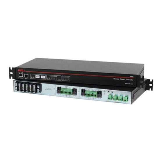
Page 4: Back Panel Components
• RPC-40L8A4-12 = + 12 V DC, 10 Amps Output Circuit Fuses - Bus A: Four 10 amp DC GMT fuses that protect circuits on Output Bus A. Ships with 10 Amp fuses; for custom fuses, please contact WTI Switched Output Circuits - Bus B: Four 10 amp DC circuits in an output terminal ... -
Page 5: Hardware Installation
RPC unit to an appropriate power source as shown in Figure 2 below. Note: RPC-40L8A4 series units feature two completely independent buses, and for each circuit, voltage is connected to the +/- terminal (for negative 48 or positive 48 volt units, power is connected to the +/- terminals and for positive 24 and 12 volt units, positive power is also connected to the +/- terminals.) - Page 6 RPC-40L8A4 Series; Quick Start Guide Connecting Switched Devices to the RPC The output terminals on the RPC back panel are used to connect DC voltage to each switched device. Each output terminal includes eight connectors (four circuits.) To connect wires to the DC output terminal block, proceed as follows: Notes: •...
- Page 7 RPC-40L8A4 Series; Quick Start Guide Output Terminal Fuses Note that each output terminal includes four fuses; one for each circuit on the output terminal. If a fuse is blown, a red dot will appear in the clear cap as shown in Figure 4.
- Page 8 RPC-40L8A4 Series; Quick Start Guide Retaining Screws Wire Alarm Wire Holes 14 to 24 Gauge Strip 0.25 Inch (6.35 mm) Gate Open Gate Closed Output Current: Input Current +48, +24 or +12 V DC Figure 5: Connecting to the Alarm Inputs...
- Page 9 RPC-40L8A4 Series; Quick Start Guide Connect your PC to the RPC Switch on power to the RPC unit; the ON LED should light, and the RDY LED should begin to flash. This indicates that the RPC is ready to receive commands.
- Page 10 RPC-40L8A4 Series; Quick Start Guide Access Command Mode: The RPC includes two separate user interfaces; the Text Interface and the Web Browser Interface. The Text Interface is available via Local PC, SSH Client, Telnet, or Modem. The Web Browser interface is only available via TCP/IP network.
- Page 11 RPC User’s Guide for important information regarding advanced configuration capabilities and more detailed operation instructions. If you have further questions regarding the RPC unit, please contact WTI Customer Support as described in the User’s Guide.
- Page 12 5 Sterling • Irvine • California 92618 (949) 586-9950 • Toll Free: 1-800-854-7226 Fax: (949) 583-9514 • www.wti.com...
Need help?
Do you have a question about the RPC-40L8A4 Series and is the answer not in the manual?
Questions and answers