
Related Manuals for WTI NPS-4HS15 Series


Summary of Contents for WTI NPS-4HS15 Series
- Page 1 WTI Part No. 14531 Rev. A NPS Series Network Power Switches - Horizontal Mount Products Covered: NPS-4HS15 Series NPS-8HS Series NPS-8HD Series NPS-H20-ATS Series NPS-16HD Series Hardware Guide...
- Page 2 Warnings and Cautions: Installation Instructions Secure Racking If Secure Racked units are installed in a closed or multi-unit rack assembly, they may require further evaluation by Certification Agencies. The following items must be considered. The ambient within the rack may be greater than room ambient. Installation should be such that the amount of air flow required for safe operation is not compromised.
- Page 3 NPS to power for bench testing and initial start up and are adequate for applications that only require 15 Amps. For 20-Amp power switching applications, please refer to the WTI Power Cable guide supplied with the unit, or use appropriate 20-Amp cables.
- Page 4 Agency Approvals FCC Part 15 Regulation This equipment has been tested and found to comply with the limits for a Class A digital device, pursuant to part 15 of the FCC Rules. These limits are designed to provide reasonable protection against harmful interference when the equipment is operated in a commercial environment.
-
Page 5: Table Of Contents
NPS-4HS15 Series - Front Panel ........ -
Page 6: Introduction
Note: For instructions regarding configuration and operation of the NPS Series Device, please refer to the WTI Firmware Guide. Model Numbers Covered This Hardware Guide discusses all WTI NPS Series products. Throughout this Hardware Guide, all of these units are referred to as the "NPS."... -
Page 7: Unit Description
PORT 3 4 5 6 7 Figure 2.1: NPS-4HS15 Series - Front Panel As shown in Figure 2.1, the NPS-4HS15 Series Front Panel includes the following components: Network Port: An RJ45 Ethernet port for connection to your 10/100/1000Base-T, TCP/IP network. Note that the Network Port also includes two, small LED indicators for Link and Data Activity. -
Page 8: Nps-4Hs15 Series - Back Panel
Unit Description 2.2. NPS-4HS15 Series - Back Panel Figure 2.2: NPS-4HS15 Series - Back Panel As shown in Figure 2.2, the NPS-4H15 Series Back Panel includes the following components: Power Inlet: Supplies power to NPS control functions and outlets. Also includes cable keeper (not shown.) -
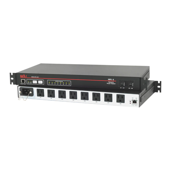
Page 9: Nps-8Hs Series - Front Panel
Unit Description 2.3. NPS-8HS Series - Front Panel NPS-8 www.wti.com Network Power Switch OUTPUT STATUS DEFAULT RESET A1 - A4 A5 - A8 SETUP PORT Figure 2.3: NPS-8HS Series - Front Panel As shown in Figure 2.3, the NPS-8HS Series Front Panel includes the following... -
Page 10: Nps-8Hs Series - Back Panel
Network Port: An RJ45 Ethernet port for connection to your 10/100/1000Base-T, TCP/IP network. Note that the Network Port also includes two, small LED indicators for Link and Data Activity. For more information on Network Port configuration, please refer to the WTI Firmware Guide. -
Page 11: Nps-8Hd Series - Front Panel
Unit Description 2.5. NPS-8HD Series - Front Panel NPS-8 www.wti.com Network Power Switch OUTPUT STATUS DEFAULT RESET A1 - A4 B1 - B4 SETUP PORT Figure 2.5: NPS-8HD Series - Front Panel As shown in Figure 2.5, the NPS-8HD Series Front Panel includes the following... -
Page 12: Nps-8Hd Series - Back Panel
Network Port: An RJ45 Ethernet port for connection to your 10/100/1000Base-T, TCP/IP network. Note that the Network Port also includes two, small LED indicators for Link and Data Activity. For more information on Network Port configuration, please refer to the WTI Firmware Guide. -
Page 13: Nps-8H20-Ats Series - Front Panel
TCP/IP network. Note that the Network Port also includes two, small LED indicators for Link and Data Activity. For more information on Network Port configuration, please refer to the WTI Firmware Guide. "ON" Indicator: An LED that lights when power is applied to the NPS. -
Page 14: Nps-8H20-Ats Series - Back Panel
Unit Description 2.8. NPS-8H20-ATS Series - Back Panel PRIMARY SECONDARY Figure 2.8: NPS-8H20-ATS Series - Back Panel As shown in Figure 2.8, the NPS-8H20-ATS Series Back Panel includes the following components: Power Inlets: Each inlet provides power to the eight switched outlets. If power to either inlet is interrupted, the NPS will automatically draw power from the remaining inlet. -
Page 15: Nps-16Hd Series - Front Panel
Unit Description 2.9. NPS-16HD Series - Front Panel NPS-16 www.wti.com Network Power Switch A1 - A4 A5 - A8 OUTPUT STATUS DEFAULT RESET B1 - B4 B5 - B8 SETUP PORT 3 4 5 Figure 2.9: NPS-16HD Series - Front Panel As shown in Figure 2.9, the NPS-16HD Series Front Panel includes the following... -
Page 16: Nps-16Hd Series - Back Panel
Unit Description 2.10. NPS-16HD Series - Back Panel LINK ALARM 10/100 BaseT Figure 2.10: NPS-16HD Series - Back Panel As shown in Figure 2.10, the NPS-16HD Series Back Panel includes the following components: Power Inlets: Each inlet provides power to the four switched outlets on the corresponding branch. Note that each inlet includes mounting hardware for the Cable Retaining clips. - Page 17 Network Port: An RJ45 Ethernet port for connection to your 10/100/1000Base-T, TCP/IP network. Note that the Network Port also includes two, small LED indicators for Link and Data Activity. For more information on Network Port configuration, please refer to the WTI Firmware Guide. 2-11...
-
Page 18: Additional Button Functions
2.11. Additional Button Functions The Default and Reset buttons on the NPS front panel can be used to perform the functions described below: Notes: • All Front Panel Button functions can also be disabled via the System Parameters menu, as described in the WTI Firmware Guide. • When the NPS is reset to factory defaults, all user-defined configuration parameters will be cleared, and the default “super” user account will also be restored. Reboot Operating System: Press and hold the Reset button for five seconds, and then release it. -
Page 19: Getting Started
Although communication via Telnet, HTTP and/or HTTPS can be enabled as described in the WTI Firmware Guide, during this bench test procedure, the NPS will be controlled via the Command Line Interface (CLI) using a local PC, connected to either the Serial SetUp Port or Network Port: • Serial SetUp Port: Use the Ethernet Cable and Adapter supplied with the NPS. -
Page 20: Communicating With The Nps
Getting Started 3.3. Communicating with the NPS Notes: • Default serial port parameters are set as follows: 9600 bps, RTS/CTS Handshaking, 8 Data Bits, One Stop Bit, No Parity. Although these parameters can be easily redefined, for this bench test procedure, it is recommended to configure your communications program to accept the default parameters. • The NPS features a default IP Address (192.168.168.168) and a default Subnet Mask (255.255.255.0.) This allows network IPv4 access to the Command Line Interface, providing that you are contacting the NPS from a node on the same subnet. Access the User Interface: Start your communications program, (e.g., Tera Term, PuTTy, etc.,) then press [Enter]. Username / Password Prompt: A message will be displayed, which prompts you to enter your username (Login) and password. -
Page 21: Hardware Installation
4. Hardware Installation This section describes the installation procedure for the NPS hardware. Note: For a detailed description of configurations options and advanced operating features, please refer to the WTI Firmware Guide. 4.1. Connecting the NPS to Your Power Supply CAUTIONS: • Before attempting to install this unit, please review the warnings and... -
Page 22: Connect The Nps To Your Power Supply
4.3.1. Connecting a Local PC Use the DX9F-WTI Adapter supplied with the unit to connect your PC COM port to the NPS Setup Port. Make certain that the Serial Port Mode is set to “Normal” as described in the WTI Firmware Guide. -
Page 23: Connecting The Network Cable
WTI Firmware Guide for important information regarding advanced configuration options, security functions and more detailed operation instructions. If you have further questions regarding the NPS unit, please contact WTI Customer Support as described in Appendix C. -
Page 24: Specifications
Appendix A. Specifications Physical/Environmental: NPS-4HS15 Series: Width: 19” (48.3 cm) (Including Rack Brackets) Depth: 4.6” (11.7 cm) Height: 1.75” (4.5 cm) One Rack U NPS-8HS Series, NPS-8HD Series, NPS-8H20-ATS Series: Width: 19” (48.3 cm) (Including Rack Brackets) Depth: 8.7” (22.1 cm) Height: 1.75” (4.5 cm) One Rack U NPS-16HD Series: Width: 19”... -
Page 25: Serial Interface Description
Appendix B. Serial Interface Description (Standard Pinout) Figure B.1: NPS Series RS232 SetUpPort Interface (RJ45 - Standard Pinout) B.1. Serial Port (RS232) DCD and DTR hardware lines function as follows: When connected: If either port is set for Modem Mode, the DTR output at either port reflects the DCD input at the other end. If neither port is set for Modem Mode, DTR output is held high (active). -
Page 26: Customer Service
If the unit should need to be returned for factory repair it must be accompanied by a Return Authorization number from Customer Service. WTI Customer Service 5 Sterling Irvine, California 92618 Local Phone: (949) 586-9950... - Page 27 Appendices Trademark and Copyright Information WTI and Western Telematic are trademarks of Western Telematic Inc.. All other product names mentioned in this publication are trademarks or registered trademarks of their respective companies. Information and descriptions contained herein are the property of Western Telematic Inc..
Need help?
Do you have a question about the NPS-4HS15 Series and is the answer not in the manual?
Questions and answers