Table of Contents
Advertisement
Quick Links
Advertisement
Table of Contents

Related Manuals for WTI AFS-16-1


Summary of Contents for WTI AFS-16-1
- Page 1 WTI Part No. 14554 Rev. A AFS-16-1 RJ45 Fallback Switch Hardware Guide...
- Page 2 Warnings and Cautions: Installation Instructions Secure Racking If Secure Racked units are installed in a closed or multi-unit rack assembly, they may require further evaluation by Certification Agencies. The following items must be considered. The ambient within the rack may be greater than room ambient. Installation should be such that the amount of air flow required for safe operation is not compromised.
- Page 3 Warnings and Cautions Two Power Supply Cables Note that some AFS series units feature two separate power inlets and a separate power supply cable for each power inlet. Make certain to disconnect all power supply cables from their power source before attempting to service or remove the unit. Disconnect Power Before Servicing Before attempting to service or remove this unit, please make certain to disconnect the power supply cable from the power source.
- Page 4 Agency Approvals FCC Part 15 Regulation This equipment has been tested and found to comply with the limits for a Class A digital device, pursuant to part 15 of the FCC Rules. These limits are designed to provide reasonable protection against harmful interference when the equipment is operated in a commercial environment.
-
Page 5: Table Of Contents
Table of Contents 1. Introduction ............. 1-1 2. -
Page 6: Introduction
1. Introduction The AFS-16-1 is a versatile switching system, designed for applications that require routing of analog or digital signals between a common RJ45 jack and “A” and “B RJ45 jacks. The AFS is ideal for switching RS232, RS422/485, Ethernet/UTP or telephone lines. -
Page 7: Unit Description
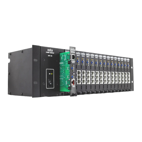
2. Unit Description The AFS consists of a frame unit, one Dual Power Supply Module, one Control Module, and up to sixteen Circuit Modules. 2.1. The Dual Power Supply Module The Dual Power Supply Module, shown in Figure 2.1, provides AC power used by the Control Module and Circuit Module(s). -
Page 8: The Control Module
Unit Description 2.2. The Control Module The Control Module, shown in Figure 2.2, coordinates switching of the individual Circuit Modules. The Control Module includes a Master A/B Gang Switch, status LEDs, a 10/100Base-T Ethernet connector and an RJ-45 RS232 Serial Port for connection to your PC, control device or external modem. - Page 9 Unit Description Reset Switch: To reinitialize the AFS, hold the Reset Switch in the "down" position for approximately five seconds. When the AFS is reset, all users will be disconnected from the AFS and the operating system will be reloaded. RS232 Connector: An RJ-45 Serial Port for connection to your PC, control device, ...
-
Page 10: The Circuit Module
Unit Description 2.3. The Circuit Module The AFS can accept up to sixteen Circuit Modules. Each Circuit Module includes a common jack, jacks for “A” and “B” paths, and a Manual A/B switch as described in Figure 2.3. RJ45-3 Figure 2.3: The Circuit Module The AFS Circuit Module includes the following components: A/B Switch: Each A/B Switch can be manually switched, or activated by ... -
Page 11: Getting Started
3. Getting Started This section describes a simplified installation procedure for the AFS hardware, which will allow you to communicate with the unit in order to demonstrate basic features and check for proper operation. Note that this Quick Start procedure does not provide a detailed description of unit configuration, or discuss advanced operating features in detail. -
Page 12: Communicating With The Afs
Getting Started 3.3. Communicating with the AFS When properly installed and configured, the AFS will allow command mode access via Telnet, Web Browser, SSH client, modem, or local PC. However, in order to ensure security, both Telnet and Web Browser access are disabled in the default state. Notes: •... -
Page 13: Fallback Switching
Getting Started Username / Password Prompt: A message will be displayed, which prompts you to enter your username (Login) and password. If a valid username and password are entered, the AFS will display either the Circuit Control Screen (Web Browser Interface) or the Circuit Status Screen (Text Interface.) Notes: •... -
Page 14: Fallback Switching - Web Browser Interface
If you have further questions regarding the AFS unit, please contact WTI Customer Support as described in Appendix C. -
Page 15: Hardware Installation
4. Hardware Installation 4.1. Connecting the Power Supply Cable(s) Refer to the cautions listed below and at the beginning of this User's Guide, and then connect the AFS to an appropriate 100 to 240 VAC power supply. CAUTIONS: • Before attempting to install this unit, please review the warnings and cautions listed at the front of this user’s guide. -
Page 16: Connecting A Local Control Device
Hardware Installation RJ-45 DB-9F Pin No. Pin No. Signal Pin 1 Pin 8 Pin 1 Female Figure 4.1: DX9F-DTE-RJ Snap Adapter Interface RJ-45 DCE DB-9M DTE Serial Port Console Port PC, Laptop or Other AFS-16 Device with Straight DB-9M DTE RJ-45 Cable Interface DX9F-DTE-RJ... -
Page 17: Module Set Up
Hardware Installation Enable Disable Figure 4.3: Circuit Module Jumper 4.5. Module Set Up 4.5.1. Circuit Module Set Up The A/B Switch Jumper on the Circuit Module card (Figure 4.3) enables/disables the individual Circuit Module’s A/B Switch. If you wish to disable manual A/B switching control at a specific Module, then the A/B Switch Jumper on that Module must be set in the "Disable"... -
Page 18: Control Module Setup
Hardware Installation High Figure 4.4: Control Module Jumper AUX Connector Control Card Jumper Pin Out Signal Ground Monitor Input Back Edge of Control Card Figure 4.5: Control Module AUX Connector - Monitor Input and Ground 4.5.2. Control Module SetUp The Control Module includes a jumper that can be used to configure the AUX Connector for use with the Monitor/Alarm Input feature. -
Page 19: Monitor Input Signal - Trigger When Low
Hardware Installation When the Monitor/Alarm Input feature is properly configured, the AFS can trigger an alarm and/or perform A/B switching operations when the signal at Pin 4 (Monitor Input) on the Control Module AUX connector goes high or low. In set up this feature, you must first use the Control Card Jumper to select the non-active (non-alarm) state, and then use the Monitor/Alarm Input configuration menu to select the active/alarm state (the signal level that will trigger an alarm) as described in the Sections that follow. -
Page 20: The A/C/B Connectors
Hardware Installation 4.6. The A/C/B Connectors Each AFS Circuit Module includes three RJ45 connectors: a "C" (Common) connector, an "A" (Primary Fallback) connector and a "B" (Secondary Fallback) connector. Use an RJ45 Ethernet cable to connect devices to the A/C/B ports as required. -
Page 21: Serial Port (Rs232)
Appendix A. Interface Description RJ-45 Pin No. Request to Send Ready Out Control Module RS232 Serial Port Data Out Pin 1 Ground Pin 8 Data In Carrier Detect Clear to Send Figure A.1: Serial Port Interface A.1. Serial Port (RS232) DCD and DTR hardware lines function as follows: When connected: If either port is set for Modem Mode, the DTR output at either port reflects the... -
Page 22: Specifications
Appendix B. Specifications Switched Circuit Card: Up to 16 Modules Interface: RJ45-3, Three Jacks, 8 Pins Switched Common Jack to A or B Jack. Contacts: High Reliability, Mechanical Relays, BreakBefore-Make Contacts with 1 Amp @ 30 VDC Rating, 100 Million Cycle Life. Switching: Manual: Individual Toggle Switch, Plus Gang Switching from Control Module. -
Page 23: Customer Service
If the unit should need to be returned for factory repair it must be accompanied by a Return Authorization number from Customer Service. WTI Customer Service 5 Sterling Irvine, California 92618 Local Phone: (949) 586-9950... - Page 24 Appendices Trademark and Copyright Information WTI and Western Telematic are trademarks of Western Telematic Inc.. All other product names mentioned in this publication are trademarks or registered trademarks of their respective companies. Information and descriptions contained herein are the property of Western Telematic Inc..
Need help?
Do you have a question about the AFS-16-1 and is the answer not in the manual?
Questions and answers