
Related Manuals for WTI IPS-800


Summary of Contents for WTI IPS-800
- Page 1 WTI Part No.: 13506 Rev. B IPS-800/1600 Series Internet Power Switches Models: IPS-800 IPS-800-CE IPS-1600 IPS-1600-CE Firmware Version: 1.41 and Higher Model IPS-800 Model IPS-1600 User’s Guide...
-
Page 3: Warnings And Cautions
Warnings and Cautions: INSTALLATION INSTRUCTIONS SECURE RACKING If Secure Racked units are installed in a closed or multi-unit rack assembly, they may require further evaluation by Certification Agencies. The following items must be considered. The ambient within the rack may be greater than room ambient. Installation should be such that the amount of air flow required for safe operation is not compromised. - Page 4 IPS-800/IPS-1600 Series - User’s Guide FCC Part 15 Regulation This equipment has been tested and found to comply with the limits for a Class A digital device, pursuant to Part 15 of the FCC rules. These limits are designed to provide reasonable protection against harmful interference in a residential installation.
-
Page 5: Table Of Contents
Table of Contents Introduction ............1-1 Unit Description . - Page 6 2.1. IPS-800 Back Panel (120 VAC Model Shown) ....... 2-1...
-
Page 7: Introduction
1. Introduction Electronic equipment sometimes "locks-up," requiring a service call just to flip the power switch to perform a simple reboot. The IPS-800/1600 Series Internet Power Switches give you the ability to perform this function from anywhere, just point your browser to the IPS’s IP address, enter the secure password, and you’re just a click away from remote power On, Off or Reboot! -
Page 8: Typographic Conventions
This User’s Guide discusses the IPS-800, IPS-1600, IPS-800-CE and IPS-1600-CE Internet Power Switches. Throughout this User’s Guide, all four units are referred to as "IPS". The IPS-800 includes eight switched 100 to 120 VAC power outlets. The IPS-1600 includes sixteen switched 100 to 120 VAC power outlets. -
Page 9: Unit Description
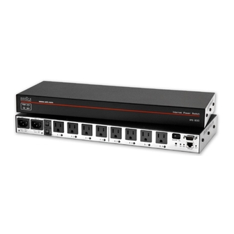
As shown in Figure 2.1 and Figure 2.2, the IPS back panel includes connectors, LEDs and manual controls described below: Figure 2.1: IPS-800 Back Panel (120 VAC Model Shown) Figure 2.2: IPS-1600 Back Panel (120 VAC Model Shown) Bus "A" Power Inlet and Circuit Breaker: An IEC-320-C14 AC inlet ➀... - Page 10 Bus "A" Switched Plugs and Plug Indicators: AC Outlets that can be ➂ switched On, Off or rebooted in response to user commands. • IPS-800: Four 100-120 VAC, NEMA 5-15 Outlets with indicator lights. 15 Amps Total Load. • IPS-1600: Eight 100-120 VAC, NEMA 5-15 Outlets with indicator lights.
-
Page 11: Quick Start
Refer to power rating nameplate on the IPS back panel, and then connect the IPS unit to an appropriate power source. The IPS-800 and IPS-1600 should be connected to a 100 to 115 VAC power supply, and the IPS-800-CE and IPS-1600-CE should be connected to a 208 to 240 VAC power supply. -
Page 12: Connect Your Pc To The Ips
IPS-800/IPS-1600 Series - User’s Guide 3.1.2. Connect your PC to the IPS The IPS can either be controlled by a local PC, that communicates with the unit via cable, controlled via external modem, or controlled via TCP/IP network. In order to switch plugs or select parameters, commands are issued to the IPS via either the Network Port or RS232 COM Port. -
Page 13: Plug Status Screen - Web Browser Interface (Ips-800 Shown)
Quick Start Figure 3.1: Plug Status Screen - Web Browser Interface (IPS-800 Shown) Internet Power Switch v1.41h Site ID: (undefined) Plug | Name | Password | Status | Boot/Seq. Delay | Default | -----+------------------+-------------+--------+-----------------+---------+ | (undefined) | (undefined) 0.5 Secs | (undefined) - Page 14 IPS-800/IPS-1600 Series - User’s Guide Access the Command Mode: This procedure differs slightly, depending on whether you’re contacting the IPS via the Web Browser Interface or Text Interface. Web Browser Interface: Start your JavaScript enabled Web Browser. Enter the IPS’s default IP address (192.168.168.168) in your browser address bar and then press [Enter].
- Page 15 Quick Start Switch Outlet On: From the Web Browser Interface, select the button in the "On" column for Plug 1, and then click "Apply." From the Text Interface, type /ON 1 and press [Enter]. The status indicator for Plug 1 should then go back On, indicating that the command has been successfully completed.
- Page 16 IPS-800/IPS-1600 Series - User’s Guide...
-
Page 17: Installation
When the cables are in place, snap the cable keepers over each plug to secure the cables to the unit. • IPS-800 and IPS-800-CE: The cable keeper for eight-plug units must be installed by the user. First make certain that both of the IPS's two power cables are disconnected from your power supply. -
Page 18: Connection To Switched Outlets
IPS unit. Note that when power is applied to the IPS, the Switched AC Outlets will be switched "ON". • IPS-800 and IPS-1600 (120 VAC Models): Units include two separate power busses. Each bus can support a total of 15 Amps. -
Page 19: Configuration
5. Configuration 5.1. System Mode and User Mode In order to restrict access to sensitive command functions, the IPS features two operating modes; System Mode and User Mode. • System Mode: Allows access to all configuration menus, switching functions and status screens. The System Mode Status Screens show On/Off conditions for all switched outlets, and lists all currently defined system parameters. -
Page 20: Communicating With The Ips
IPS-800/IPS-1600 Series - User’s Guide Figure 5.1: Plug Status Screen - Web Browser Interface (IPS-800 Shown) 5.2. Communicating with the IPS In order to configure the unit or invoke command functions, you must first connect to the IPS and access command mode. As discussed in Section 3, the IPS offers two separate command interfaces: the Web Browser Interface, and the Text Interface. -
Page 21: Accessing The Text Interface
Confi guration Password Prompt: The IPS will display a prompt, which asks for your name and password. User Name: If you have not previously defined a user name, then this field should be left blank. A user name is only required when one has been defined via the General Parameters menu. -
Page 22: Plug Status Screen - Text Interface (Ips-800 Shown)
-----+------------------+-------------+--------+-----------------+---------+ “/H” for help. IPS> Figure 5.2: Plug Status Screen - Text Interface (IPS-800 Shown) Via Network: The IPS includes a default IP address (192.168.168.168), which allows you to contact the unit from any network node on the same subnet. When the IPS is installed in a working network environment, it is recommended to redefine the... -
Page 23: Configuration Menus
Confi guration 5.3. Configuration Menus As described in the sections that follow, configuration parameters for the IPS can be selected via the Web Browser Interface or Text Interface. Although the Web Browser and Text Interface provide two separate means for selecting parameters, both interfaces allow access to essentially the same set of parameters, and parameters selected via one interface will also be applied to the other. -
Page 24: The General Parameters Menus
IPS-800/IPS-1600 Series - User’s Guide Figure 5.3: General Parameters Menu - Web Browser Interface 5.3.1. The General Parameters Menus The General Parameters Menus allow you to select parameters such as the System Password, User Name, Site I.D. and other options. -
Page 25: General Parameters Menu - Text Interface
Confi guration GENERAL PARAMETERS: System Password: (undefined) User Name: (undefined) Site ID: (undefined) Command Echo: Inactivity Timeout: 2 Mins Command Confirmation: Automated Mode: Manual Switch Button: On Command Prompt: Default Parameters Enter Selection, Press <ESC> to Exit ... Figure 5.4: General Parameters Menu - Text Interface •... - Page 26 IPS-800/IPS-1600 Series - User’s Guide • Inactivity Timeout: Determines how long the IPS will wait for additional commands during periods of inactivity. When the Timeout Period elapses, the user will be disconnected from the IPS command mode. (Default = 2 Minutes.) •...
-
Page 27: The Serial Parameters Menu
Confi guration Figure 5.5: Serial Parameters Menu - Web Browser Interface SERIAL PARAMETERS: 1. Baud Rate: 9600 2. Data: 8 Bit 3. Parity: None 4. Stop: 1 Bit 5. Port Mode: Console 6. Modem Init. Str: ATE0M0Q1&C1&D2S0=1 Enter selection, Press <ESC> to return to previous menu ... Figure 5.6: Serial Parameters Menu - Text Interface 5.3.2. - Page 28 IPS-800/IPS-1600 Series - User’s Guide As shown in Figure 5.5 and Figure 5.6, the Serial Parameters Menus allow you to define the following parameters: • Baud Rate: Baud Rate for the IPS COM Port. (Default = 9600 bps.) Note: When this setting is changed, the new baud rate will not be applied until the user exits and then re-enters command mode.
-
Page 29: Plug Parameters Menus
Confi guration Figure 5.7: Plug Parameters Menu - Web Browser Interface PLUG #1 PARAMETERS: 1. Plug Name: (undefined) 2. Password: (undefined) 3. Boot/Seq. Delay: 0.5 Secs 4. Power Up Default: Enter Selection, Press <ESC> to Exit ... Figure 5.8: Plug Parameters Menu - Text Interface (Plug 1 Shown) 5.3.3. -
Page 30: Plug Passwords And Co-Location Features
IPS-800/IPS-1600 Series - User’s Guide The Plug Parameters Menu allows you to define the following parameters: • Plug Name: (Up to 16 Characters, Default = undefined.) Note: Plug Names cannot begin with a number, dash (-), underscore character (_), forward slash character (/) or backslash (\) character, and cannot include non printable characters, spaces, asterisks (*), colons (:), the plus symbol (+) or quotation marks. -
Page 31: The Boot / Sequence Delay Period
Confi guration 5.3.3.2. The Boot / Sequence Delay Period. The Boot / Sequence Delay value will be applied differently for Reboot operations as opposed to simple On/Off operations as described below: Reboot Cycles: Single Plug: The Boot/Seq. Delay determines how long the plug will remain Off before it is switched back On again. -
Page 32: Network Parameters Menu - Web Browser Interface
IPS-800/IPS-1600 Series - User’s Guide Figure 5.9: Network Parameters Menu - Web Browser Interface NETWORK PARAMETERS: 1. IP Address: 192.168.168.168 2. Subnet Mask: 255.255.255.0 3. Gateway Address: (undefined) 4. Send MSS: 5. IP Security MAC Address: 00-09-9b-00-a0-32 Enter Selection, Press <ESC> to Exit ... -
Page 33: Network Parameters Menus
Confi guration 5.3.4. Network Parameters Menus The Network Parameters Menus are used to select the IP Address and other network parameters. • Web Browser Interface: Click the "Setup" button to access the Setup Menus, and then click the "Network Parameters" button. The Network Parameters Menu will be displayed as shown in Figure 5.9. -
Page 34: Ip Security Feature
IPS-800/IPS-1600 Series - User’s Guide IP SECURITY: Security Mask #1: (undefined) Mask #1 Action: Permit Security Mask #2: (undefined) Mask #2 Action: Permit Security Mask #3: (undefined) Mask #3 Action: Permit Security Mask #4: (undefined) Mask #4 Action: Permit Security Mask #5: (undefined) - Page 35 Confi guration Example 1: Deny access to all hosts except 192.1.1.5: Security Mask #1: 255.255.255.255 Mask #1 Action: Deny Security Mask #2: 192.1.1.5 Mask #2 Action: Permit Since 255 is a wild card, Mask #1 blocks all IP Addresses. Mask #2 then specifically grants access to 192.1.1.5 only.
-
Page 36: The Telnet Parameters Menus
IPS-800/IPS-1600 Series - User’s Guide Figure 5.12: Telnet Parameters Menu - Web Browser Interface TELNET PARAMETERS: 1. Service: 2. Telnet Port #: Enter Selection, Press <ESC> to Exit ... Figure 5.13: Telnet Parameters Menu - Text Interface 5.3.5. The Telnet Parameters Menus The Telnet Parameters Menus are used to enable/disable Telnet access to the IPS command mode and select the TCP port for Telnet connections. -
Page 37: Web Server Parameters Menus
Confi guration Figure 5.14: Web Server Parameters Menu - Web Browser Interface WEB SERVER: 1. Service: 2. Server Port #: Enter Selection, Press <ESC> to Exit ... Figure 5.15: Web Server Parameters Menu - Text Interface 5.3.6. Web Server Parameters Menus The Web Server Parameters Menus are used to configure the internal web server, which allows the unit to be operated via the Web Browser Interface. -
Page 38: Save Configuration Parameters
IPS-800/IPS-1600 Series - User’s Guide 5.4. Save Configuration Parameters The IPS offers two methods for saving parameters; Saving to Memory, and Saving to an ASCII File. Saving parameters to memory ensures that your user-defined configuration will remain intact if power to the IPS is temporarily interrupted. After the configuration menus have been used to change parameters, the IPS will prompt... -
Page 39: Operation
6. Operation As discussed in Section 5, the IPS offers two separate command interfaces; the Web Browser Interface and the Text Interface. Note that Both interfaces offer essentially the same command options and features, and that parameters defined via the Web Interface will also apply when communicating via the Text Interface (and vice versa.) 6.1. -
Page 40: Plug Status Menu - Web Browser Interface (Ips-800 Shown)
IPS-800/IPS-1600 Series - User’s Guide Figure 6.1: Plug Status Menu - Web Browser Interface (IPS-800 Shown) Switching Plugs On: Click the "On" radio button next to the desired plug(s), then click "Apply". To switch all Plugs On, click the "On" radio button in the "All Plugs"... -
Page 41: Operation Via The Text Interface
-----+------------------+-------------+--------+-----------------+---------+ “/H” for help. IPS> Figure 6.2: Plug Status Screen - Text Interface (IPS-800 Shown) 6.2. Operation via the Text Interface When using the Text Interface, all switching functions are performed by invoking simple, ASCII commands. ASCII commands are also used to display status screens and to log out of command mode. -
Page 42: Switching And Reboot Commands - Text Interface
IPS-800/IPS-1600 Series - User’s Guide Internet Power Switch v1.41h Site ID: (undefined) Display Configuration Display Help Screen View/Set General Parameters Display Plug Status /P [n] View/Set Plug Parameters Display Network Status View/Set Serial Parameters View/Set Network Parameters Control View/set Telnet Parameters... - Page 43 Operation To Switch Plugs, or initiate a Boot Cycle, proceed as follows: Switch Plug(s) On: To power-on a plug, type /ON n and press [Enter]. Where "n" is the number or name of the desired plug. For example: /ON 1 or /ON ROUTER Switch Plug(s) Off: To power-off a plug, type /OFF n and press [Enter].
-
Page 44: Applying Commands To Several Plugs - Text Interface
IPS-800/IPS-1600 Series - User’s Guide 6.2.3. Applying Commands to Several Plugs - Text Interface As described below, switching and reboot commands can be applied to only one Switched AC Outlet, or to an assortment of outlets. Note: When switching and reboot operations are initiated, Boot/ Sequence Delay times will be applied as described in Section 5.3.3.2. -
Page 45: The Automated Mode
Operation 6.4. The Automated Mode The Automated Mode allows the IPS to execute switching and reboot commands, without displaying menus or generating response messages. Automated Mode is designed to allow the IPS to be controlled by a device which can generate commands to control power switching functions without human intervention. -
Page 46: Manual Operation
IPS-800/IPS-1600 Series - User’s Guide "Sure?" Prompt Suppressed: All commands are executed without prompting for user confirmation. Error Messages Suppressed: If the [Enter] key is pressed without entering a command, the IPS will not respond with the "Invalid Command" message. Note however, that an error message will still be generated if commands are invoked using invalid formats or arguments. -
Page 47: Saving And Restoring Configuration Parameters
7. Saving and Restoring Configuration Parameters After the IPS has been properly configured, parameters can be downloaded and saved as an ASCII text file on your local or remote PC. Later, if the configuration is accidentally altered, the file with the saved parameters can be uploaded to automatically reconfigure the unit without the need to manually assign each parameter. -
Page 48: Restoring Saved Parameters
IPS-800/IPS-1600 Series - User’s Guide 7.2. Restoring Saved Parameters This Section describes the procedure for using your communications program to send saved parameters to the IPS. Note: Parameters saved to an ASCII file can only be restored via the Text Interface. This procedure cannot be performed via the Web Browser Interface. -
Page 49: Upgrading The Ips Firmware
Obtain the update file. Firmware modifications can either be mailed to the customer on a CDR, or downloaded from WTI. Place the upgrade CDR in your disk drive or copy the file to your hard drive. - Page 50 Port to 9600 bps, Eight Data Bits, No Parity, One Stop Bit, and then return to step 3 above and repeat the upload procedure. When firmware upgrades are available, WTI will provide the necessary files via download or mailed CDROM. At that time, an updated Users Guide or...
-
Page 51: Interface Description
A. Interface Description A.1. Serial COM / RS232 Port Interface Figure A.1: COM Port Interface Apx-1... -
Page 52: Specifications
▪ Depth: 7.0” (17.8 cm) ▪ Height: 3.5” (8.9 cm) 2 Rack U • Shipping Weight: ▪ Models IPS-800 & IPS-800-CE: 10 lbs (4.5 Kg) ▪ Models IPS-1600 & IPS-1600-CE: 12 lbs (5.5 Kg) • Operating Temperature: 32°F to 122°F (0°C to 50°C) •... -
Page 53: Customer Service
If the unit should need to be returned for factory repair it must be accompanied by a Return Authorization number from Customer Service. WTI Customer Service 5 Sterling Irvine, California 92618... - Page 54 IPS-800/IPS-1600 Series - User’s Guide Trademark and Copyright Information WTI and Western Telematic are trademarks of Western Telematic Incorporated. All other product names mentioned in this publication are trademarks of their respective companies. Information and descriptions contained herein are the property of Western Telematic, Inc..
-
Page 55: Index
Index 100Base-T Data Bits 5-10 10Base-T Default Button 2-2, 5-8 Default Command Default IP Address Activity Indicator Delay Period 5-13 Automated Mode 5-8, 6-7 to 6-8 Deny 5-16 Baud Rate 5-10 Error Messages Boot/Sequence Delay 5-12 to 5-13 Ethernet Port 2-2, 4-2 Bus A External Modem... - Page 56 IPS-4 Internet Power Switch; User’s Guide Service ON Indicator Customer Service Apx-3 Operation 6-1 to 6-8 Telnet 5-18 Web Browser Interface 6-1 to 6-2 Web Server 5-19 Site I.D. Specifications Apx-2 Parity 5-10 Status Indicators Passwords 5-4, 6-7 Stop Bits 5-10 Plug 5-1, 5-12...
- Page 57 Notes: Notes-1...
- Page 58 IPS-800/IPS-1600 Series - User’s Guide Notes Notes-2...
- Page 60 5 Sterling Irvine California 92618 • • (949) 586-9950 Toll Free: 1-800-854-7226 • Fax: (949) 583-9514 http://www.wti.com •...
Need help?
Do you have a question about the IPS-800 and is the answer not in the manual?
Questions and answers