
Related Manuals for WTI RPC Series


Summary of Contents for WTI RPC Series
- Page 1 WTI Part No. 14533 Rev. A RPC Series Remote DC Power Control Switches Products Covered: RPC-4850 Series RPC-40L8A4 Series Hardware Guide...
- Page 2 Two Power Supplies Note that RPC series units feature two separate power circuits and a separate power supply cable for each power inlet. Make certain to disconnect all power supply cables from their power source before attempting to service or remove the unit.
-
Page 3: Table Of Contents
Table of Contents 1. Introduction ............. 1-1 2. Unit Description . -
Page 4: Introduction
1. Introduction This Hardware Guide covers set-up and installation for our RPC Series Network Power Switches. RPC Series units are designed to simplify the process of remotely managing vital network elements located at distant network equipment sites and off-site facilities by providing secure remote access to DC power switching and reboot functions at the remote network equipment site. -
Page 5: Unit Description
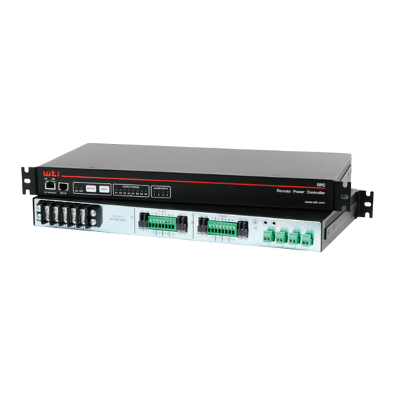
2. Unit Description 2.1. Front Panel Components - RPC-4850 Series www.wti.com Remote Power Controller RPC-4850 CIRCUITS CONTROL Figure 2.1: Front Panel (Model RPC-4850-48V Shown) As shown in Figure 2.1, the RPC-4850 Series Front Panel includes the following: Circuit Status Indicators: A series of eight LED indicators, which light when power to the corresponding circuit is Switched On. -
Page 6: Back Panel Components - Rpc-4850 Series
TCP/IP network. Note that the Network Port also includes two, small LED indicators for Link and Data Activity. For information on Network Port configuration, please refer to the WTI Firmware Guide. Console Port: A DB9, RS232 serial port (DTE), for connection to a local terminal or external modem, as described in Section 4.6. -
Page 7: Front Panel Components - Rpc-40L8A4 Series
Switched On. Alarm Input Indicators: A series of four LED indicators which light when the corresponding Alarm Input has generated an alarm. For more information on Alarm Input functions, please refer to Section 4.5 and the WTI Firmware Guide. -
Page 8: Back Panel Components - Rpc-40L8A4 Series
WTI. Optional Grounding Lug Location: Mounting holes for optional grounding lug for 6 gauge ground wire. For more information, please contact WTI. Alarm Inputs: Four Euro style alarm inputs, which are designed for connection to door open alarms or other dry contacts. Each alarm input supplies 0.4 Amps of positive DC current at the same voltage that is used to power the unit (e.g., ± 48 V... -
Page 9: Additional Button Functions
Additional Button Functions The Default and Reset buttons on the RPC front panel can be used to perform the functions described below: Notes: • All Front Panel Button functions can also be disabled via the System Parameters menu, as described in the WTI Firmware Guide. • When the RPC is reset to factory defaults, all user-defined configuration parameters will be cleared, and the default “super” user account will also be restored. Reboot Operating System: Press and hold the Reset button for five seconds, and then release it. -
Page 10: Getting Started
Section 4.1 and RPC-40L8A4 series units are discussed in Section 4.2. • For more information regarding installing the RPC hardware in a working network environment, please refer to Section 4. • For instructions regarding configurations options and advanced operating features, please refer to the WTI Firmware Guide. 3.1. Apply Power to the RPC Unit 3.1.1. Connecting RPC-4850 Series Units to Power Refer to power rating nameplate on the back panel, and then connect the RPC-4850 series unit to an appropriate power source The RPC-4850 features two separate DC inputs;... -
Page 11: Connecting Rpc-40L8A4 Series Units To Power
Although communication via Telnet, HTTP and/or HTTPS can be enabled as described in the WTI Firmware Guide, during this bench test procedure, the RPC will be controlled via the Command Line Interface (CLI) using a local PC, connected to either the Serial SetUp Port or Network Port: • Serial SetUp Port: Use the Ethernet Cable and Adapter supplied with the RPC. -
Page 12: Controlling Power Circuits
User’s Guide for important information regarding advanced configuration capabilities and more detailed operation instructions. If you have further questions regarding the RPC unit, please contact WTI Customer Support as described in Appendix C. -
Page 13: Hardware Installation
4. Hardware Installation 4.1. Applying Power to RPC-4850 Series Units Note: This procedure differs for RPC-40L8A4 series units. For instructions on connecting power to RPC-40L8A4 series units, please refer to Section 4.2. Refer to power rating nameplate on the back panel, and then connect the RPC-4850 series unit to an appropriate power source as shown in Figure 4.1. RPC-4850 series units features two separate DC inputs; connect power cables to the unit's Circuit "A"... - Page 14 Hardware Installation -48 VDC INPUT A 0 VDC -48 VDC INPUT B (CIRCUIT 0 VDC BREAKER) OUTPUT -48 VDC CKT 1 0 VDC -48 VDC OUTPUT CKT 2 0 VDC B BUS A BUS (-48 VDC) CIRCUITS 3 - 8 Figure 4.1: Model RPC-4850 Series Block Diagram (Model RPC-4850-48V Shown)
-
Page 15: Applying Power To Rpc-40L8A4 Series Units
Hardware Installation 4.2. Applying Power to RPC-40L8A4 Series Units Note: This procedure differs for RPC-4850 series units. For instructions on connecting power to RPC-4850 series units, please refer to Section 4.1. Refer to power rating nameplate on the back panel, and then remove the protective cover from the terminal block and connect the RPC-40L8A4 unit to an appropriate power source as shown in Figure 4.2 and Figure 4.3. CAUTIONS: •... - Page 16 Hardware Installation ±48 VDC INPUT A 0 VDC ±48 VDC INPUT B 0 VDC OUTPUT ±48 VDC CKT A1 0 VDC ±48 VDC OUTPUT CKT A4 0 VDC OUTPUT ±48 VDC CKT B1 0 VDC OUTPUT ±48 VDC CKT B4 0 VDC Figure 4.3: RPC-40L8A4 Series Units;...
-
Page 17: Connecting Switched Devices To Rpc-4850 Series Units
Hardware Installation 4.3. Connecting Switched Devices to RPC-4850 Series Units Note: This procedure differs for RPC-40L8A4 series units. For instructions on connecting switched devices to RPC-40L8A4 series units, please refer to Section 4.4. Make certain that the power supply to the RPC-4850 series unit is switched Off, and then connect the supply cables from your DC powered devices to the Switched Output Circuits on the RPC-4850 back panel. -
Page 18: Output Terminal Fuses
To remove a fuse, use a pair of pliers to grasp the black body of the fuse, and then gently pull the fuse loose from the RPC-40L8A4 unit. The RPC-40L8A4 ships with 10 Amp fuses; for custom fuses, please contact WTI. Red Dot... -
Page 19: Connecting To The Alarm Inputs (Rpc-40L8A4 Units Only)
RPC-40L8A4 unit. Caution: Do not over tighten the retaining screws. The recommended maximum torque is 4.5 lbf-in (72 ozf-in.) Note: For instructions regarding configuration of the Alarm Input Alarm, please refer to the WTI Firmware Guide. Retaining Screws Wire Alarm Wire... -
Page 20: Serial Console / Rs232 Port Connection
Use the supplied null modem cable to connect your computer console port to the RPC SetUp (RS232) Port. Make certain that the Serial Port Mode is set to "Normal" (the default setting) as described in the WTI Firmware Guide. 4.6.2. -
Page 21: Emergency Shut Off Function
4.8. Emergency Shut Off Function RPC Series units also include an Emergency Shut Off function, that can be used to immediately shut off all RPC power circuits in case of emergency. For more information regarding the Emergency Shut Off feature, please contact WTI Tech Support at service@wti.com. -
Page 22: Specifications
Appendix A. Specifications Physical/Environmental: RPC-4850 Series: Width: 19” (48.3 cm) (Including Rack Brackets) Depth: 9.5” (24.1 cm) Height: 3.5” (8.8 cm) Two Rack U RPC-40L8A4 Series: Width: 19” (48.3 cm) (Including Rack Brackets) Depth: 9.5” (24.1 cm) Height: 1.75” (4.5 cm) One Rack U Operating Temperature: 32˚F to 122˚F (0˚C to 50˚C) Humidity: 10 - 90% RH Apx-1... -
Page 23: Serial Interface Description
Appendix B. Serial Interface Description Figure B.1: RPC Series RS232 SetUpPort Interface (RJ45 - Standard Pinout) B.1. Serial Port (RS232) DCD and DTR hardware lines function as follows: When connected: If either port is set for Modem Mode, the DTR output at either port reflects the DCD input at the other end. -
Page 24: Customer Service
If the unit should need to be returned for factory repair it must be accompanied by a Return Authorization number from Customer Service. WTI Customer Service 5 Sterling Irvine, California 92618 Local Phone: (949) 586-9950... - Page 25 Appendices Trademark and Copyright Information WTI and Western Telematic are trademarks of Western Telematic Inc.. All other product names mentioned in this publication are trademarks or registered trademarks of their respective companies. Information and descriptions contained herein are the property of Western Telematic Inc..
Need help?
Do you have a question about the RPC Series and is the answer not in the manual?
Questions and answers