YOKOGAWA UT150 User Manual
Ut100 series
Hide thumbs
Also See for UT150:
- Technical information (86 pages) ,
- User manual (4 pages) ,
- Instruction manual (14 pages)
Advertisement
Table of Contents
- 1 Table of Contents
- 2 Temperature Controller
- 3 User's Manual (IM 05C01E12-01E)
- 4 Notice
- 5 What Is on the Front Panel
- 6 Installing the Controller
- 7 Panel Cutout Dimensions and External Dimensions
- 8 Wiring
- 9 Hardware Specifications
- 10 Key Operations
- 11 Troubleshooting
- Download this manual
See also:
Technical Information
Advertisement
Table of Contents

Related Manuals for YOKOGAWA UT150


Summary of Contents for YOKOGAWA UT150
- Page 1 User’s Models Manual UT150, UT152, UT155 Temperature Controllers IM 05C01E12-41E IM 05C01E12-41E 2004.6 4th Edition...
- Page 2 Therefore, both manuals have the same contents, except for some minor differences in the cross- referenced page numbers. Revision Record Manual No. : IM 05C01E12-41E(4th Edition) Title : Models UT150,UT152,UT155 Temperature Controllers Revised Item Edition Date First Newly published Nov.,2000...
-
Page 3: Table Of Contents
Note:When specifying the /RS option, be sure to order the required number of copies of Communication Functions User’s Manual separately. Check the package contents against the list below......• Temperature controller ........ • Mounting bracket 1 for UT150 2 for UT152, UT155 ..• User’s manual (IM 05C01E12-01E) IM 05C01E12-41E... -
Page 4: Notice
Yokogawa Electric Corporation assumes no liability to any party for any loss or damage, direct or indirect, caused by the use or any unpredictable defect of the instrument. -
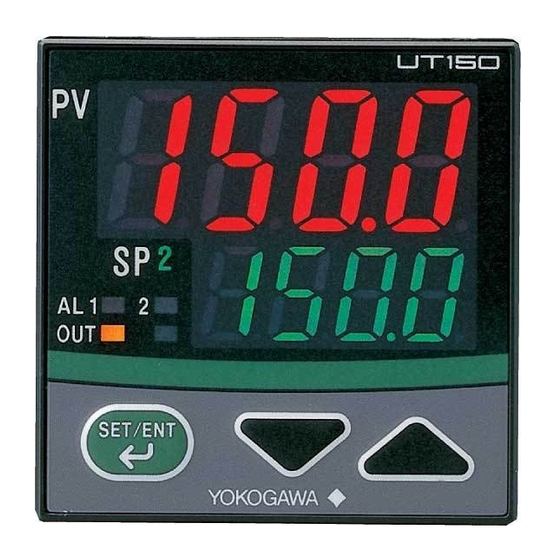
Page 5: What Is On The Front Panel
Lit when SP2 is being used for control operation. Output (OUT) display lamps Lit while control output is being output. UT150: (Left: orange; right: green) • The left (upper) lamp is lit in orange during control output of standard type. UT152, UT155: •... -
Page 6: Installing The Controller
Mount the controller at an angle within 30 from horizontal with the screen facing upward. Do not mount it facing downward. 30° (MAX) Mounting the Controller Large bracket UT150 UT152, UT155 (top) Panel 1. Affix the bracket over the back 2. Push the bracket to the panel, and then secure the bracket end of the controller. -
Page 7: Panel Cutout Dimensions And External Dimensions
EXTERNAL DIMENSIONS NOTE Splash-proof construction is not available when the side-by-side close mounting method shown in the following figures, is chosen for any of the controllers. 1. General Mounting min. 70 UT150 Unit: mm +0.6 2. Side-by-side Close Mounting × +0.6 [(N –1) -
Page 8: Wiring
NOTE • Always fix a terminal cover bracket to the UT150 controller before wiring if an optional anti-electric- shock terminal cover (part number: L4000FB) is used. • Two types of optional anti-electric-shock terminal covers (part numbers T9115YE and T9115YD) are available for the UT152 and UT155 controllers, respectively. - Page 9 UT150 Terminal Arrangement (Standard type) Universal input-selectable Retransmission Output Heater Current Detection Input Alarm Outputs Measured Value (PV) Input input type ALM2 TC Input RTD Input DC mV or V Input ALM1 – (Note 1) – – When “/RET” When “/HBA”...
- Page 10 UT152/UT155 Terminal Arrangement (Standard type) Note: The terminal arrangements of the UT152 and UT155 are the same. Universal input-selectable Measured Value (PV) Input input type Parameter DIS External Contact Inputs 0 (Default) TC Input RTD Input DC mV or V Input Timer starts Timer starts RUN/STOP...
-
Page 11: Hardware Specifications
Personal computer link: Used for communication with a personal computer, or UT Applicable standards: Thermocouple and resistance temperature detector JIS/IEC/DIN (ITS90) link module of the FA-M3 controller (from Yokogawa Electric Corporation). • Ladder communication: Used for communication with a ladder communication module of the FA-M3, or a programmable controller of other manufacturers. - Page 12 /EX option are isolated from the internal circuit. Construction, Mounting, and Wiring • Construction: Dust-proof and drip-proof front panel conforming to IP65 [Model UT150] and IP55 [Models UT152 and UT155]. For side-by-side close installation the controller loses its dust-proof and drip-proof protection. •...
-
Page 13: Key Operations
When “In” appears, press the key to display the measured input range code you want to use, then press the key to register it. After this operating, the controller shows the operating display UT150/UT152/UT155 Measured Input Ranges °C °C °F °F Input type Range... - Page 14 CAUTION To prevent electric shock, the controller should be mounted on the panel so that you do not accidentally touch the terminals when power is being applied. NOTE The temperature controller is shipped with the parameters set at the factory-set defaults. Check the default values against the “Parameter Lists”...
- Page 15 Changing Target Setpoint (SP) Changing Alarm 1 Setpoint (A1) This setpoint appears only if the /AL or /HBA option is specified.) The following instructions assume that the Step 1: controller is already receiving power. Confirm that the controller shows the operating display Step 1: 1 during normal operation Confirm that the controller...
- Page 16 Power ON NOTE When measured input range code has been already set, the operating display 1 shown below appears. is displayed Operating display NOTE When “In” appears, press the Measured input value (PV) key to display the measured input SP1 or SP2 value can be changed In STOP mode, at operating display 1 Target setpoint (SP1 or SP2)
-
Page 17: Parameter Lists
Parameter Lists Numbers in ( ) are the parmeter setpoints that apply when the (1) Target Setpoint (SP) and Timer Setting 1 and 2 communication function is used. Ex. OFF(0), ON(1) Code Name Setting range and unit Default User setting (SP value display) Target Minimum value (SPL) to maximum value (SPH) of target setpoint range... -
Page 18: Ut155
Set the ramp-rate time unit using parameter TMU. down-rate 0 : °C or °F / hour Setpoint ramp- 1 : °C or °F / min rate time unit External Contact Inputs Parameter DIS UT150 UT152 UT155 Timer starts Timer starts RUN/STOP STOP when DI=ON when DI=ON... - Page 19 Alarm Function List Alarm Alarm Action Action type code type code “Opn” and “Cls” indicate that the relay contact is “Opn” and “Cls” indicate that the relay contact is Alarm type Alarm type opened and closed; “(on)” and “(off)” indicate that opened and closed;...
-
Page 20: Description Of Parameters
Description of Parameters This section describes the parameter functions specific to the UT150/UT152/UT155 temperature controllers. (The functions described in other sections of this manual and the general functions are not discussed.) Parameter Function Parameter Function Control mode Select one from the following:... - Page 21 What is Dynamic Auto Tune Control? Dynamic auto tune control is one of the features offered by the temperature controller. When the controller is turned on or the process variable (PV) starts “hunting”, this mode of control monitors the behavior of the PV and/or OUT (control output value) to automatically determine the optimum PID constants. This means that the PID constants may be changed automatically.
-
Page 22: Troubleshooting
TROUBLESHOOTING In the event of an abnormality, perform the following checks as outlined by the flowchart. Is the controller defective? Communication Completely inactive? Key operation failure? Display failure? I/O signal failure? failure? Check the terminal connection Check key-lock Turn the power off, Verify the I/O spec. - Page 24 Sales Branch Offices / Houten (The Netherlands), Wien (Austria), Zaventem (Belgium), Ratingen (Germany), Madrid (Spain), Bratislava (Slovakia), Runcorn (United Kingdom), Milano (Italy), Velizy villacoublay(France), Johannesburg(Republic of South Africa) YOKOGAWA AMERICA DO SUL S.A. Headquarters & Plant Praca Acapulco, 31-Santo Amaro, Sao Paulo/SP, BRAZIL CEP-04675-190 Phone: +55-11-5681-2400 Facsimile: +55-11-5681-4434 YOKOGAWA ENGINEERING ASIA PTE.
Need help?
Do you have a question about the UT150 and is the answer not in the manual?
Questions and answers