Table of Contents
Advertisement
Advertisement
Table of Contents

Related Manuals for Tennant 6600


Summary of Contents for Tennant 6600
- Page 1 6600 Operator Manual 330950 Rev. 02 *330950* Home Find... Go To..
- Page 2 This manual is furnished with each new TENNANT Model 6600. It provides necessary operating and preventive maintenance instructions. Read this manual completely and understand the machine before operating or servicing it. This machine will provide excellent service. However, the best results will be obtained at minimum costs if: D The machine is operated with reasonable care.
-
Page 3: Table Of Contents
TO REPLACE MAIN BRUSH ..PRESSURIZER SWITCH (OPTION) TO CHECK AND ADJUST MAIN BRUSH PATTERN ... . 6600 330950 (3- -05) Home Find... Go To.. - Page 4 ....... . . 6600 330950 (3- -05) Home Find... Go To..
-
Page 5: Safety Precautions
- - Turn off machine and remove key. WARNING: Hot surface. keep away CAUTION: LPG engine will run for a few seconds after key is turned off. Apply parking brake before leaving machine. 6600 330950 (3- -05) Home Find... Go To.. - Page 6 Keep area well ventilated. - - Use cardboard to locate leaking hydraulic fluid under pressure. - - Use TENNANT supplied or approved replacement parts. 7. When loading/unloading machine onto/off truck or trailer: - - Turn off machine.
- Page 7 COMPARTMENT. HOPPER LIFT ARMS LABEL - - LOCATED ON BOTH HOPPER HOPPER SUPPORT BAR LABEL - - LOCATED LIFT ARMS. ON THE HOPPER SUPPORT BAR AND ON BOTH HOPPER LIFT ARMS. 354000 6600 330950 (3- -05) Home Find... Go To..
-
Page 8: Operation
- Gasoline powered machines: Fill the fuel tank. FOR SAFETY: When servicing machine, keep flames and sparks away from fuel system service area. Keep area well ventilated. 6600 330950 (4- -03) Home Find... Go To.. - Page 9 We recommend taking advantage of a regularly scheduled service contract from your TENNANT representative. - Order parts and supplies directly from your authorized TENNANT representative. Use the parts manual provided when ordering parts. 6600 330950 (4- -03) Home Find... Go To..
-
Page 10: Machine Components
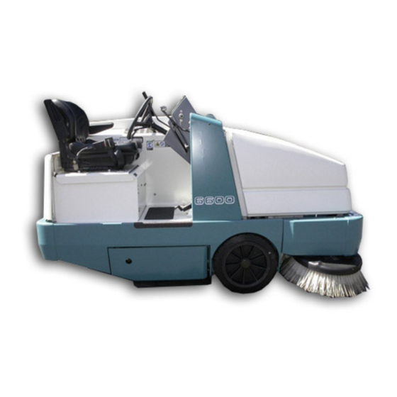
MACHINE COMPONENTS 354000 A. Steering Wheel B. Operator Seat C. Engine Cover D. Engine Side Door E. Main Brush Access Door F. Hopper Access Cover G. Side Brush H. Hopper Cover Instrument Panel 6600 330950 (4- -03) Home Find... Go To.. -
Page 11: Control Panel Symbols
Hopper Door Closed Horn LPG Fuel Main Brush Down Pressure Light Hourmeter Main Brush Down Pressure Heavy Hazard Light Main Brush Float Filter Shaker Main Brush Down Operating Lights Main Brush Up 6600 330950 (4- -03) Home Find... Go To.. - Page 12 Side Brush Down Pressure Heavy Side Brush Up Windshield Wiper Slow Windshield Wiper Fast Dome Light Heater Cab Pressurizer Slow Cab Pressurizer Fast Engine speed (idle) Engine speed (slow) Engine speed (fast) 6600 330950 (4- -03) Home Find... Go To..
-
Page 13: Controls And Instruments
T. Engine Oil Pressure Light (For Machines Serial Number 024999 And Below) U. Hopper Temperature Light -- Thermo Sentryt V. Charging System Light W. LP Fuel Light X. Check Engine Light Y. Fuel Gauge (Gasoline Machines Only) Z. Fuses 6600 330950 (2- -04) Home Find... Go To.. -
Page 14: Operation Of Controls
Reverse: Press the bottom of the directional pedal with the heel of your foot. Neutral: Take your foot off the directional pedal and it will return to the neutral position. 6600 330950 (4- -03) Home Find... Go To.. -
Page 15: Brake Pedal
Set: Pull the parking brake lever up. FOR SAFETY: Before leaving or servicing machine; stop on level surface, set parking brake, turn off machine and remove key. Release: Push the parking brake lever down. 6600 330950 (4- -03) Home Find... Go To.. -
Page 16: Main Brush And Side Brush Lever
On position. NOTE: Always raise the main brush when the machine is not being operated for some time. This prevents the main brush from getting a flat spot. 6600 330950 (4- -03) Home Find... Go To.. -
Page 17: Hopper Door Lever
Close: Pull and hold the hopper door lever into the Close position. NOTE: The hopper door will not close if the main brush, side brush, and vacuum fan are operating. 6600 330950 (4- -03) Home Find... Go To.. -
Page 18: Hopper Lift Lever
NOTE: The hopper will not raise if the main brush, side brush, and vacuum fan are operating. Hold: Release the hopper lift lever up and into the middle position. Down: Push and hold the hopper lift lever into the Down position. 6600 330950 (4- -03) Home Find... Go To.. -
Page 19: Main Brush Position Lever
Up: Pull the main brush position lever all the way back and to the right. Release the lever forward into the Up position. HORN BUTTON The horn button operates the horn. Sound: Press the button. 6600 330950 (4- -03) Home Find... Go To.. -
Page 20: Main Brush Adjustment Knob
Secure adjustment knob: Turn the adjustment plate knob clockwise until the knob is hand tight and the plate cannot slide in the adjustment panel. 6600 330950 (4- -03) Home Find... Go To.. -
Page 21: Turn Signal Switch (Option)
TURN SIGNAL SWITCH (OPTION) The turn signal switch operates the turn signals. Right: Push the switch lever forward. 06487 Left: Pull the switch lever back. 06488 Flashers: Pull out the knob. 06745 6600 330950 (4- -03) Home Find... Go To.. -
Page 22: Hopper Temperature Light - - Thermo Sentry
HOPPER DOOR LIGHT The hopper door light comes on when the hopper door is closed. Make sure the hopper door is open and the hopper door light is off, before sweeping with the machine. 6600 330950 (4- -03) Home Find... Go To.. -
Page 23: Engine Oil Pressure Light
Stop sweeping with the machine, and return the machine to the service area. Replace the empty LPG fuel tank with a full tank. See the CHANGING THE LPG TANK section of the manual. 6600 330950 (2- -04) Home Find... Go To.. -
Page 24: Clogged Filter Light
35 kPa (5psi). If the check engine light comes on while operating the machine, contact a TENNANT service representative to enter the CHECK ENGINE FAULT MODE, and determine the fault. 6600 330950 (2- -04) -
Page 25: Hourmeter
LPG powered machine: The fuel level gauge on the LPG tank indicates how much fuel is in the LPG tank. 6600 330950 (2- -04) Home Find... Go To.. -
Page 26: Operating/Hazard Lights Switch
The light in the top half of the switch will turn on. Stop Vacuum Fan: Press the switch to the middle off position. Start Filter Shaker: Press the bottom of the switch. The shaker will operate for approximately 10 seconds. 6600 330950 (4- -03) Home Find... Go To.. -
Page 27: Engine Speed Switch
Medium (Fast 1): Press the engine speed switch to the middle position. This speed is for general sweeping. High (Fast 2): Press the top of the engine speed switch. This speed is for sweeping light litter. 6600 330950 (4- -03) Home Find... Go To.. -
Page 28: Steering Wheel
STEERING COLUMN TILT LEVER (OPTION) The steering column tilt lever controls the angle of the steering column. Adjust: Pull down on the tilt lever, move the column up or down, and release the tilt lever. 6600 330950 (4- -03) Home Find... Go To.. -
Page 29: Ignition Switch
NOTE: To protect the engine’s emission components on LPG powered machines serial number 025000 and above, the engine will continue to operate for a few seconds after the ignition switch is turned off. 6600 330950 (3- -05) Home Find... Go To.. -
Page 30: Side Brush Position Lever
Release the lever up into the Brush Down slot. Side Brush Up: Pull the side brush position lever down and to the left. Release the lever up into the Brush Up slot. 6600 330950 (4- -03) Home Find... Go To.. -
Page 31: Side Brush Down Pressure Knob
The side brush down pressure knob changes the side brush contact with the sweeping surface. Heavy: Turn the side brush down pressure knob counter-clockwise. Light: Turn the side brush down pressure knob clockwise. 6600 330950 (4- -03) Home Find... Go To.. -
Page 32: Fuses
F-12 15 A Reverse switch F-13 Open F-14 Open F-15 Open F-16 Open F-17 Open F-18 Open F-19 15 A Vacuum fan, filter shaker, indicator lights F-20 15 A Headlights, Warning lights 6600 330950 (2- -04) Home Find... Go To.. -
Page 33: Circuit Breakers (Option)
The chart lists the circuit breakers and the electrical components they protect. Circuit Breaker Rating Circuit Protected CB-21 20 A Air conditioner (option) CB-22 20 A Air conditioner (option) 6600 330950 (2- -04) Home Find... Go To.. -
Page 34: Latches
Tilt out Hydraulic Cooler: On machines serial number 025000 and above, lift up on the rear of the latch and release the front of the latch from the catch. 6600 330950 (2- -04) Home Find... Go To.. -
Page 35: Hopper Support Bar
Lift: Pull up on the operator seat mounting plate until the seat mount locks up. Lower: Pull on the release lever and lower the seat mounting plate. 6600 330950 (4- -03) Home Find... Go To.. -
Page 36: Deluxe Suspension Seat (Option)
Adjust: Pull the lever in, slide the seat forward or backwards to the desired position, and release the lever. The weight adjustment lever controls the firmness of the operator’s seat. 6600 330950 (2- -04) Home Find... Go To.. -
Page 37: Heater Knob (Option)
The wiper can be operated at two speeds. Slow: Press the top of the switch. Fast: Press the bottom of the switch. Off: Return the switch to the middle position. 6600 330950 (4- -03) Home Find... Go To.. -
Page 38: Dome Light Switch (Option)
The pressurizer can be operated at two speeds. Slow: Press the top of the switch. Fast: Press the bottom of the switch. Off: Return the switch to the middle position. 6600 330950 (4- -03) Home Find... Go To.. -
Page 39: How The Machine Works
- Check the condition of the hopper dust filter and seals. Clean as required. - Check the brakes and steering for proper operation. - Check the fuel level. - Check the service records to determine if maintenance is needed. 6600 330950 (3- -05) Home Find... Go To.. -
Page 40: Changing An Lpg Fuel Tank
NOTE: If you cannot line up the centering pin, make sure you have the correct LPG fuel tank and then adjust the pin locator in or out. 7. Fasten the tank hold-down clamp to lock the tank in position. 6600 330950 (4- -03) Home Find... Go To.. - Page 41 9. Open the tank service valve slowly and check for leaks. Close the service valve immediately if an LPG leak is found, and tell the appropriate personnel. 6600 330950 (4- -03) Home Find... Go To..
-
Page 42: Starting The Machine
WARNING: Engine emits toxic gases. Severe respiratory damage or asphyxiation can result. Provide adequate ventilation. Consult with your regulatory authorities for exposure limits. Keep engine properly tuned. 6600 330950 (4- -03) Home Find... Go To.. - Page 43 OPERATION 5. Release the machine parking brake. 6. Select the (Fast 1) engine speed with the engine speed switch. 7. Drive the machine to the area being swept. 07816 6600 330950 (4- -03) Home Find... Go To..
-
Page 44: Sweeping And Brush Information
This brush is recommended for foundry sweeping where heat may melt synthetic bristles. This brush has good hopper loading ability, but is not recommended for dusty applications. 6600 330950 (4- -03) Home Find... Go To.. -
Page 45: Sweeping
SWEEPING 1. Select an engine speed. 2. Make sure the hopper door light is off. If the hopper door light is on, open the hopper door. 6600 330950 (4- -03) Home Find... Go To.. - Page 46 Release the lever forward into the Down position. 6. Pull the side brush position lever back and to the right. Release the lever up into the Down slot. 7. Sweep as needed. 6600 330950 (4- -03) Home Find... Go To..
-
Page 47: Stop Sweeping
2. Pull the side brush position lever down and to the left. Release the lever up into the Up slot. 3. Pull the main brush and side brush lever into the middle (Off) position. 6600 330950 (4- -03) Home Find... Go To.. - Page 48 OPERATION 4. Pull the hopper door lever into the Close position until the hopper door light comes 5. Press the filter shaker switch to activate the hopper filter shaker. 6600 330950 (4- -03) Home Find... Go To..
-
Page 49: Emptying The Hopper
1. Slowly drive the machine to the debris site or debris container. 07816 2. Pull the hopper door lever into the Close position until the hopper door light comes 3. Release the hopper door lever into the middle (Hold) position. 6600 330950 (4- -03) Home Find... Go To.. - Page 50 8. Push the hopper door lever into the Open position and leave it there. 9. Raise the hopper enough and/or close the hopper door to clear the top of the debris container. 6600 330950 (4- -03) Home Find... Go To..
- Page 51 10. Slowly back the machine away from the debris site or debris container. For Safety: When using machine, use care when reversing machine. 07999 11. Push the hopper lift lever into the Down position. 6600 330950 (4- -03) Home Find... Go To..
-
Page 52: Stop The Machine
1. Stop sweeping. 2. Take your foot off the directional pedal. Step on the brake pedal. 3. Select the (Idle) position with the engine speed switch. 4. Set the machine parking brake. 6600 330950 (4- -03) Home Find... Go To.. - Page 53 025000 and above, the engine will continue to operate for a few seconds after the ignition switch is turned off. 6. LPG powered machines: Close the LPG tank’s liquid service valve. 6600 330950 (3- -05) Home Find... Go To..
-
Page 54: Post-Operation Checklist
- Check the sweeping brush patterns for adjustment. - Check the brakes and steering for proper operation. - Check the fuel level - Check the service records to determine maintenance requirements. 6600 330950 (4- -03) Home Find... Go To.. -
Page 55: Engaging Hopper Support Bar
1. Set the machine parking brake. 2. Start the engine. For Safety: When starting machine, keep foot on brake and directional pedal in neutral. 3. Raise the hopper all the way up. 6600 330950 (4- -03) Home Find... Go To.. - Page 56 Engage hopper support bar. 5. Slowly lower the hopper so the lift arm rests on the support bar. WARNING: Lift arm pinch point. Stay clear of hopper lift arms. 6. Shut the engine off. 6600 330950 (4- -03) Home Find... Go To..
-
Page 57: Disengaging Hopper Support Bar
2. Raise the hopper slightly to release the hopper support bar. 3. Put the support bar in its storage position. WARNING: Lift arm pinch point. Stay clear of hopper lift arms. 6600 330950 (4- -03) Home Find... Go To.. -
Page 58: Operation On Inclines
Drive the machine slowly on inclines. Use the brake pedal to control machine speed on descending inclines. The maximum rated incline is 6_. FOR SAFETY: When using machine, go slow on inclines and slippery surfaces. 6600 330950 (2- -04) Home Find... Go To.. -
Page 59: Options
4. Release the rubber strap(s) from the top edge of the vacuum hose. 5. On machines without a cab, lift the hose handle off the support hook and remove the hose end from the support hook. 6600 330950 (2- -04) Home Find... Go To.. - Page 60 7. On machines without a cab, disconnect the rubber straps securing the solid section of vacuum hose to the machine. On machines with a cab, disconnect the rubber straps securing the vacuum hose handle to the machine. 6600 330950 (2- -04) Home Find... Go To..
- Page 61 Select the (Fast 2) engine speed with the engine speed switch. 10. Pull and hold the hopper door lever into the Close position until the hopper door light comes on. 6600 330950 (4- -03) Home Find... Go To..
- Page 62 OPERATION 11. Press the vacuum fan switch to start the vacuum. 12. Vacuum the area as needed. 13. Press the vacuum switch to shut off the vacuum. 6600 330950 (4- -03) Home Find... Go To..
- Page 63 15. Open the hopper cover. 16. Remove the vacuum hose from the hopper connection and close the vacuum wand door. 17. Secure the vacuum wand and hose in place with the mounting clips and rubber strap(s). 6600 330950 (2- -04) Home Find... Go To..
-
Page 64: Blower Wand
2. Move the lever on the engine cover forward into the ON position to start airflow through the wand. 08144 3. Direct the wand into the area of debris. The operator can rest the wand on the side bracket. 08147 6600 330950 (4- -03) Home Find... Go To.. -
Page 65: Heater Valve
The valve controls the flow of hot coolant to the heater core. The amount of coolant that flows through the heater valve is controlled with the heater knob in the cab (option). 6600 330950 (4- -03) Home Find... Go To.. -
Page 66: Machine Troubleshooting
Hopper lip skirts worn or damaged Replace lip skirts Hopper door partially or Open the hopper door completely closed Wrong sweeping brush Contact TENNANT representative for recommendations Main brush in Down position Put main brush in Float position 6600 330950 (4- -03) Home Find... Go To.. - Page 67 OPERATION 6600 330950 (2- -04) Home Find... Go To..
-
Page 68: Maintenance
Clean core exterior Check coolant level Hydraulic fluid reservoir Check fluid level HYDO Rear tire Check pressure Main brush and hopper Check for damage or wear seals Engine crankcase Change oil and filter element 6600 330950 (3- -05) Home Find... Go To.. - Page 69 HYDO Tennant Company or approved hydraulic fluid . . . Water and permanent-type ethylene glycol anti-freeze, --34_ C (--30_ F) . . . Special lubricant, Lubriplate EMB grease (TENNANT part no. 01433--1) 6600 330950 (3- -05) Home Find... Go To..
-
Page 70: Lubrication
The rear wheel support pivots the rear wheel. The support has two grease fittings for the bearings. The rear wheel support bearings must be lubricated every 200 hours of operation. Use Lubriplate EMB grease (TENNANT part no. 01433--1). 6600 330950 (2- -04) Home Find... Go To.. -
Page 71: Hopper Bearings
The hopper bearings must be lubricated after every 200 hours of operation. Use Lubriplate EMB grease (TENNANT part no. 01433--1). FRONT WHEEL BEARINGS Inspect the front wheel bearings for seal damage, and repack and adjust every 400 hours of operation. -
Page 72: Hydraulics
The quality and condition of the hydraulic fluid play a very important role in how well the machine operates. TENNANT’s hydraulic fluid is specially selected to meet the needs of TENNANT machines. 6600 330950 (4- -03) Home Find... Go To.. -
Page 73: Hydraulic Hoses
MAINTENANCE TENNANT’s hydraulic fluids provide a longer life for the hydraulic components. There are two fluids available for different temperature ranges: TENNANT part no. Ambient Temperature 65869 above 7_ C (45_ F) 65870 below 7_ C (45_ F) The higher temperature fluid has a higher viscosity and should not be used at the lower temperatures. -
Page 74: Engine
Replace the hoses and clamps if the hoses are cracked, harden, or swollen. Flush the radiator and the cooling system every 800 hours of operation, using a dependable cleaning compound. 6600 330950 (2- -04) Home Find... Go To.. -
Page 75: Air Filter
Replace the air filter element only when the air filter indicator shows restriction in the air intake system. Do not remove the air filter element from the housing unless it is restricting air flow. 6600 330950 (3- -05) Home Find... Go To.. -
Page 76: To Replace Air Filter
7. Install the new filter by hand. Make certain that the new filter is all the way in the housing, and seated evenly before latching the dust cap in place. 8. Close the side door and engine cover. 6600 330950 (4- -03) Home Find... Go To.. -
Page 77: Fuel Filter (Gasoline)
Replace the fuel filter element on machines serial number 025000 and above after every 400 hours of operation. FOR SAFETY: When servicing machine, keep flames and sparks away from fuel system service area. Keep area well ventilated. 6600 330950 (3- -05) Home Find... Go To.. -
Page 78: Electronic Fuel Injection (Efi)
The intake and exhaust valve clearances need no adjustment. CRANKCASE VENTILATION SYSTEM Replace the oil fill cap after every 400 hours of operation. TIMING BELT Replace the engine timing belt every 1000 hours of operation. 6600 330950 (3- -05) Home Find... Go To.. -
Page 79: Battery
A static drag chain prevents the buildup of static electricity in the machine. The chain is attached to the machine by a rear main brush skirt retaining bolt. Make sure the chain is touching the floor at all times. 6600 330950 (4- -03) Home Find... Go To.. -
Page 80: Debris Hopper
NOTE: Be sure the dust filter is dry before reinstalling it in the machine. 6600 330950 (4- -03) Home Find... Go To.. -
Page 81: To Replace Hopper Dust Filter
4. Lift the dust filter element assembly out from the hopper. 5. Cut the four cable ties that are holding the filter shaker plate to the element. 6600 330950 (4- -03) Home Find... Go To.. - Page 82 9. Place the filter shaker plate onto the new or cleaned dust filter element. Make sure the lip on the filter shaker plate is fastened over the lip on the dust filter element. 6600 330950 (4- -03) Home Find... Go To..
-
Page 83: Thermo Sentry
If there is a fire in the hopper, the Thermo Sentry stops the vacuum fan and cuts off the air flow. Reset the Thermo Sentry by pushing in its reset button. 6600 330950 (4- -03) Home Find... Go To.. -
Page 84: Brushes
Rotate the main brush end-for-end every 50 hours of operation for maximum brush life and best sweeping performance. Replace the main brush when the remaining bristles measure 50 mm (2.0 in) in length. 6600 330950 (4- -03) Home Find... Go To.. -
Page 85: To Replace Main Brush
Secure the plate in position with the brush idler plate latch. Close the right side main brush access door. 6600 330950 (4- -03) Home Find... Go To.. -
Page 86: To Check And Adjust Main Brush Pattern
(2.0 to 2.5 in). 00582 9. To increase the width of the main brush pattern, loosen the main brush adjustment knob and slide the main brush adjustment plate forward 7 to 14 mm (0.25--0.50 in). 6600 330950 (4- -03) Home Find... Go To.. - Page 87 C. Check the main brush pattern and readjust as necessary. Set the main brush adjustment knob to match the same color band as the brush idler plate. 6600 330950 (4- -03) Home Find... Go To..
-
Page 88: Side Brush
50 mm (2 in) in length. You may change the side brush sooner if you are sweeping light litter, or wear the bristles shorter if you are sweeping heavy debris. 6600 330950 (4- -03) Home Find... Go To.. -
Page 89: To Replace Side Brush
11. Adjust the side brush pattern with the side brush down pressure knob. SIDE BRUSH GUARD Rotate the side brush guard 90_ every 200 hours of operation. Replace the brush guard after all four sides have been used. 6600 330950 (4- -03) Home Find... Go To.. -
Page 90: Skirts And Seals
NOTE: The brush door skirts have slotted holes to allow for a ground clearance adjustment. The door must be closed for proper adjustment. NOTE: Rear tire pressure will affect skirt clearances. 6600 330950 (4- -03) Home Find... Go To.. -
Page 91: Rear Skirts
BRUSH DOOR SEALS The brush door seals are located on both main brush doors and on corresponding portions of the main frame. Check the seals for wear or damage every 100 hours of operation. 6600 330950 (4- -03) Home Find... Go To.. -
Page 92: Hopper Seals
The hopper door seals are located on the hopper door. They seal the hopper when the hopper door is closed. Check the seals for wear or damage every 100 hours of operation. 6600 330950 (4- -03) Home Find... Go To.. -
Page 93: Hopper Filter Seals
(option). It seals the vacuum wand opening when the vacuum wand (option) is not in use. Check the seal for wear or damage every 100 hours of operation. 6600 330950 (3- -05) Home Find... Go To.. -
Page 94: Brakes And Tires
Torque the rear wheel nuts in a star pattern twice to 142 to 157 Nm (105 to 115 ft. lb) after the first 50-hours of operation, and every 800 hours there after. 6600 330950 (4- -03) Home Find... Go To.. -
Page 95: Pushing, Towing, And Transporting The Machine
1. Position the rear of the machine at the loading edge of the truck or trailer. FOR SAFETY: Use truck or trailer that will support the weight of the machine. NOTE: Empty the hopper before transporting the machine. 6600 330950 (4- -03) Home Find... Go To.. - Page 96 Do not drive the machine onto the truck or trailer unless the loading surface is horizontal AND is 380 mm (15 in) or less from the ground. 6600 330950 (4- -03) Home Find... Go To..
- Page 97 Do not drive the machine off the truck or trailer unless the loading surface is horizontal AND 380 mm (15 in) or less from the ground. 6600 330950 (4- -03) Home Find... Go To..
-
Page 98: Machine Jacking
Before storing the machine for an extended period of time, the machine needs to be prepped to lessen the chance of rust, sludge, and other undesirable deposits from forming. Contact TENNANT service personnel. 6600 330950 (4- -03) Home Find... Go To.. -
Page 99: Specifications
10_ (Full Hopper), 15_ (Empty Hopper) TIRES Location Type Size Pressure Front (2) Solid 5 x 18 in Rear (1) Pneumatic 6 x 19 in 790 + 35 kPa (115 + 5 psi) 6600 330950 (2- -04) Home Find... Go To.. -
Page 100: Power Type
HYDRAULIC SYSTEM System Capacity Fluid Type Hydraulic reservoir 24.6 L (6.5 gal) TENNANT part no. 65869 -- above 7_ C (45_ F) TENNANT part no. 65870 -- below 7_ C (45_ F) Hydraulic total N/A L (N/A gal) BRAKING SYSTEM Type... -
Page 101: Machine Dimensions
2360 mm (93 in) 1590 mm (62.5 in) TOP VIEW 2080 mm (82 in) 1475 mm (58 in) 1135 mm (44.75 in) 1560 mm (61.5 in) SIDE VIEW FRONT VIEW 354037 MACHINE DIMENSIONS 6600 330950 (4- -03) Home Find... Go To.. - Page 102 SPECIFICATIONS 6600 330950 (2- -04) Home Find... Go To..
-
Page 103: Index
Pressurizer switch, 36 Heater knob (option), 35 Side brush down pressure knob, 29 Pressurizer switch, 36 Side brush position lever, 28 Windshield wiper switch, 35 Steering column tilt lever, 26 Steering wheel, 26 6600 330950 (3- -05) Home Find... Go To.. - Page 104 Crankcase ventilation system, 76 Lift, 16 Electronic fuel injection (EFI), 76 Lip skirts, 88 Fan belt, 77 Seals, 90 Fuel filter (Gasoline), 75 Side skirt, 88 Fuel filter (LPG), 75 Support bar, 33 6600 330950 (3- -05) Home Find... Go To..
- Page 105 Main brush and side brush lever, 14 Engine side door, 32 Main brush position lever, 17 Grille doors, 32 Maintenance, 66–87 Right rear, 32 Intervals, 66–67 Hopper cover, 32 Recommended, 7 Hydraulic cooler, 32 Main brush doors, 32 6600 330950 (3- -05) Home Find... Go To..
- Page 106 Coolant level, 6, 72 Tires, 97 Coolant type, 72 Fins, 37, 52 Starting the machine, 40–41 Flushing system, 72 Static drag chain, 77 Hoses, 72 Steering, 37, 52 Rear wheel, 92 Specifications, 98 6600 330950 (3- -05) Home Find... Go To..
- Page 107 Transporting machine, 93 Transporting the machine, 93 Travel speed, 97 Troubleshooting, 64 Turn signal switch, 19 Vacuum fan/filter shaker switch, 24 Vacuum wand, 57–62 Valve tappet clearance, 76 Windshield wiper switch, 35 6600 330950 (3- -05) Home Find... Go To..
- Page 108 INDEX 6600 330950 (3- -05) Home Find... Go To..
Need help?
Do you have a question about the 6600 and is the answer not in the manual?
Questions and answers