Table of Contents
Advertisement
Quick Links
Download this manual
See also:
User Manual
Advertisement
Table of Contents

Subscribe to Our Youtube Channel
Related Manuals for Sena ProBee-ZU10


Summary of Contents for Sena ProBee-ZU10
-
Page 1: User Guide
ProBee-ZU10 User Guide Rev.1.0 ZigBee USB Adapter ProBee-ZU10 User Guide Sena Technologies, Inc. Rev 1.0... - Page 2 This device is not approved for life-support or medical systems. Changes or modifications to this device not explicitly approved by Sena Technologies will void the user's authority to operate this device.
-
Page 3: Table Of Contents
ProBee-ZU10 User Guide Rev.1.0 Contents INTRODUCTION ....................... 8 About This Document ........................ 8 Overview ...........................8 GETTING STARTED....................10 Hardware Installation ....................... 10 2.1.1 Panel Layout ........................10 2.1.2 USB Driver Installation ...................... 11 Configuration ........................... 11 2.2.1 Button ..........................11 Using Terminal Software for AT Commands................ - Page 4 ProBee-ZU10 User Guide Rev.1.0 4.1.4 Sending Binary Data ......................24 4.1.5 Display Incoming Message ....................24 Data Mode..........................25 4.2.1 Unicast Data Mode ......................25 4.2.2 Multicast Data Mode ......................27 4.2.3 Broadcast Data Mode ....................... 29 AT COMMAND REFERENCE................. 31 Command Line Format ......................
- Page 5 ProBee-ZU10 User Guide Rev.1.0 5.5.2 AT+ESCAN or AT+ES ....................... 36 5.5.3 AT+DSCAN or AT+DS ...................... 36 5.5.4 AT+NODETYPE or AT+NT....................37 5.5.5 AT+PERMIT or AT+PJ ...................... 37 5.5.6 AT+LEAVE or AT+LV ......................37 End-device ..........................37 5.6.1 AT+SLEEP or AT+SM ....................... 37 5.6.2...
- Page 6 ProBee-ZU10 User Guide Rev.1.0 6.1.4 Sleepy End-device ......................43 6.1.5 Specifying Network ......................43 Data Transmission ........................44 6.2.1 Command Mode ....................... 44 6.2.2 Data Mode........................44 UART Settings ......................... 45 Security ........................... 46 Firmware Upload ........................46 6.5.1 Local Node ........................46 6.5.2...
- Page 7 ProBee-ZU10 User Guide Rev.1.0 7.5.2 S62........................... 54 MECHANICAL DRAWINGS..................55 WARRANTY......................56 GENERAL WARRANTY POLICY ..................... 56 LIMITATION OF LIABILITY ...................... 56 HARDWARE PRODUCT WARRANTY DETAILS ..............56 SOFTWARE PRODUCT WARRANTY DETAILS ..............57 THIRD-PARTY SOFTWARE PRODUCT WARRANTY DETAILS ..........57 REGULATORY INFORMATION................
-
Page 8: Introduction
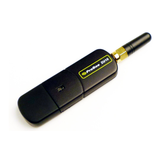
Introduction About This Document This document provides an introduction on configuration and operation of the ProBee-ZU10 ZigBee USB Adapter. This document assumes the user is using the ZU10 adapter for evaluation hence the pictures and configuration examples shown in this document are all based on the ZU10 adapter. - Page 9 ProBee-ZU10 User Guide Rev.1.0 Applications Advanced Metering Infrastructure Home Area Networks (HAN) Neighborhood Area Networks (NAN) Home Automation Advanced lighting, entertainment, and climate control systems Service-based monitoring, security, and awareness systems Commercial Building Automation ...
-
Page 10: Getting Started
ProBee-ZU10 User Guide Rev.1.0 Getting Started Creating a ZigBee network using the ZU10 adapters consists of the following steps: Connect the ZU10 adapter to a computer Create a ZigBee network by configuring a ZU10 adapter as the coordinator ... -
Page 11: Usb Driver Installation
ProBee-ZU10 User Guide Rev.1.0 2.1.2 USB Driver Installation In case the USB interface is used for the communication between the development board and the computer, the corresponding software driver needs to be installed on the computer. Windows XP and later versions already include the USB driver. - Page 12 ProBee-ZU10 User Guide Rev.1.0 Figure 2-3 HyperTerminal Serial Settings To display the AT commands that are being typed, you need to enable the local echo option on the HyperTerminal. To enable this option, Go to File->Properties->Settings->ASCII setup and select the “Echo typed characters locally”...
-
Page 13: Using Probee Manager For Configuration
ProBee-ZU10 User Guide Rev.1.0 Using ProBee Manager for Configuration Figure 2-5 ProBee Manager It is possible to set or get the configurations of the ZU10 using ProBee Manager. This PC utility helps that a user can configure several setting values easily without a terminal program and upload the firmware file... -
Page 14: Zigbee Network Configuration
ProBee-ZU10 User Guide Rev.1.0 ZigBee Network Configuration A ZigBee Network consists of a coordinator, routers and end devices. A minimal ZigBee network consists of one coordinator and multiple end devices which directly connect to the coordinator. For larger ZigBee networks, routers are required to provide redundant routings to form mesh networks. -
Page 15: Node Type Selection For Coordinator
ProBee-ZU10 User Guide Rev.1.0 Configure the ZU10 node type as the coordinator Optionally, select the channel mask. Otherwise, the ZU10 will use the default channel mask. Optionally, set up the PAN ID and/or the extended PAN ID. Otherwise, the ZU10 will generate the PAN ID and/or the extended PAN ID automatically. -
Page 16: Pan Id Configuration For Coordinator
ProBee-ZU10 User Guide Rev.1.0 Table 3-2 Channel Bitmask Channel Bit mask 00001000 00002000 00004000 00008000 00010000 00020000 00040000 Channel Bit mask 00080000 00100000 00200000 00400000 00800000 01000000 02000000 3.1.3 PAN ID Configuration for Coordinator Every ZigBee network should be assigned a PAN ID to identify the network. If the PAN ID is 0000, the ZU10 will generate a random 16-bit PAN ID to start the ZigBee network. -
Page 17: Setting Up Zu10 As A Router
ProBee-ZU10 User Guide Rev.1.0 The user can permit joining for a moment at need. The AT command to permit joining is AT+PERMIT= n or AT+PJ=n Where n is the duration to permit in seconds ranging 1~254 seconds. The ZU10 permits joining for the duration that is configured in S-register 22 (S22). The AT command to... -
Page 18: Channel Mask Configuration For Router
ProBee-ZU10 User Guide Rev.1.0 Example) AT+NODETYPE=2<CR> # Select router mode OK<CR> # Response ATZ<CR> # Apply the change OK<CR> # Response 3.2.2 Channel Mask Configuration for Router When the ZU10 as a ZigBee router or a ZigBee end device tries to join, it scans all the channels configured by channel mask to find the ZigBee network to join. -
Page 19: Setting Up Zu10 As A Sleepy End Device
ProBee-ZU10 User Guide Rev.1.0 Configure the ZU10 node as an end device Optionally, select the channel mask. Otherwise, the ZU10 will use the default channel mask. Optionally, set up the PAN ID and/or the extended PAN ID. Otherwise, the ZU10 will scan and join the ZigBee network found automatically. - Page 20 ProBee-ZU10 User Guide Rev.1.0 One of the unique features of the ZigBee device is its extreme low power consumption which is mainly achieved by its efficient sleep and wake-up mechanism. While ZigBee coordinator and routers are required to be in operation always, ZigBee sleepy end devices can be configured to be in the sleep mode most of the time and only wake up at pre-configured time interval for data transmission before it goes into the sleep mode again.
-
Page 21: Zigbee Security
ProBee-ZU10 User Guide Rev.1.0 Parent Node Sleep Wake-Up Sleep Sleepy End Device Poll Request Data Exchange Figure 3-1 Sleep Interval and Wake-up Timing The sleepy end device can also wake up from the sleep mode by incoming serial data. Once it wakes up, it also polls with the parent node at S52 interval and goes into sleep mode after S54 time elapses after the last data exchange. -
Page 22: Security Level
ProBee-ZU10 User Guide Rev.1.0 3.5.1 Security Level In order to use security in the application, a user should set security level using the AT command below. Set 1 defines both Authentication and Encryption at the network layer. Set 0 defines no security. Disabling security in the application is not ZigBee compliant. -
Page 23: Data Transmission
ProBee-ZU10 User Guide Rev.1.0 Data Transmission The ZU10 supports three different types of data transmissions: unicast, multicast and broadcast. Unicast is to transmit data to a specific ZigBee device. Multicast is to transmit data to a group of ZigBee devices that are assigned a specific group ID. -
Page 24: Broadcast
ProBee-ZU10 User Guide Rev.1.0 ATS36=n, where n is the radius. ATS37=n, where n is the number of hops through nonmembers. 4.1.3 Broadcast Broadcast transmissions are sent from a source device to all devices in the ZigBee network. The AT command for the broadcast transmissions is as below. -
Page 25: Data Mode
ProBee-ZU10 User Guide Rev.1.0 the data mode, on the other hand, incoming data is always displayed. To change the S11 register, please use the AT command as below: ATS11=<value><CR>, where <value> = 0 to hide incoming message, 1 to show incoming message. - Page 26 ProBee-ZU10 User Guide Rev.1.0 ATD<CR> Set unicast data mode to the preconfigured destination IEEE address without reset. ATD<value><CR> Set unicast data mode and <value> can be either 16-bit node ID or 64-bit IEEE address of remote node. AT+TRANSMITMODE=1<CR> Set the transmit mode to unicast to a destination IEEE address. The device should be reset to apply the mode.
-
Page 27: Multicast Data Mode
ProBee-ZU10 User Guide Rev.1.0 AT+TRANSMITMODE=1<CR> # Set transmit mode to destination IEEE address OK<CR> # Response ATZ<CR> # Apply to change OK<CR> # Response Send unicast msg # Put the unicast message # Leave data mode OK<CR> # Response AT+TRANSMITMODE=4<CR>... - Page 28 ProBee-ZU10 User Guide Rev.1.0 Set multicast data mode to preconfigured destination group ID without reset. ATM<value><CR> Set multicast data mode and <value> can be 16-bit group ID. AT+TRANSMITMODE=2<CR> Set the transmit mode to multicast mode. The device should be reset to apply the mode.
-
Page 29: Broadcast Data Mode
ProBee-ZU10 User Guide Rev.1.0 4.2.3 Broadcast Data Mode Broadcast data mode can be used for continuous data transmission to all devices in the current network. The destination address or group ID of the remote nodes is not necessary for broadcast data mode. The transmit range is determined by the S-register 35. - Page 30 ProBee-ZU10 User Guide Rev.1.0 ATZ<CR> # Apply to change OK<CR> # Response Send broadcast msg # Put the broadcast message # Leave data mode OK<CR> # Response...
-
Page 31: At Command Reference
ProBee-ZU10 User Guide Rev.1.0 AT Command Reference Command Line Format Each command line is composed of a prefix, body and terminator. Only “AT” can be used for the prefix. The body is a string of characters. The terminator is <CR> or <NL>. A command can be one of the followings: ... -
Page 32: Ate
ProBee-ZU10 User Guide Rev.1.0 5.2.4 Description Echo(1) or No Echo(0). Execute ATE<number><CR> Response OK<CR> 5.2.5 Enter the multicast mode. If there’ s no argument after the command, it will connect to Description the preconfigured destination group ID. Every data is packetized at intervals of inter character timeout(S12). -
Page 33: Node Specific Information
ProBee-ZU10 User Guide Rev.1.0 5.2.11 +++ Description Interrupt data mode. “+++” must be entered within 500ms. Execute Response OK<CR> Node Specific Information 5.3.1 AT+LONGADDR or AT+LA Get the 64-bit IEEE address. (EUI address, long address) The IEEE address is a Description unique device address assigned during manufacturing. -
Page 34: At+Oppanid Or At+Oi
ProBee-ZU10 User Guide Rev.1.0 5.3.5 AT+OPPANID or AT+OI Get the operating 16-bit PAN ID. If PAN ID is set specific value not 0s, operating PAN Description ID will equal designated PAN ID. A value of “FFFF” means the device is not joined a network. -
Page 35: At+Panid Or At+Pi
ProBee-ZU10 User Guide Rev.1.0 Range 00001000 - 03FFF000 5.4.2 AT+PANID or AT+PI Get/Set the 16-bit PAN ID. If it is set to 0s, the coordinator will select a random 16-bit Description hexadecimal number as PAN ID, and the router/end-device will join any existing network if it is allowed. -
Page 36: At+Nodename Or At+Nn
ProBee-ZU10 User Guide Rev.1.0 that should join the same network. (0: Network specific, 1: ZigBee, 2: ZigBee Pro) Execute AT+STACK?<CR> AT+STACK=<value><CR> <value><CR> Response OK<CR> or ERROR<CR> OK<CR> Default Range 0 - 2 5.4.7 AT+NODENAME or AT+NN Get/Set the node name. It can be used to make a clear distinction role or functionality Description of local node from others. -
Page 37: At+Nodetype Or At+Nt
ProBee-ZU10 User Guide Rev.1.0 AT+DSCAN=<scan duration><CR> or AT+DSCAN=<scan duration>,<node type><CR> or AT+DSCAN=<scan duration>,<node type>,<node name><CR> <node type>|<IEEE address>|<node ID>|<version>|<product name>|<node name> Response List of the existing nodes and information… OK<CR> Scan duration: 1 – 10 Range Node type: 0 – 4 (Zero indicates all node types.) 5.5.4... -
Page 38: At+Parentsa Or At+Ps
ProBee-ZU10 User Guide Rev.1.0 <IEEE address><CR> Response OK<CR> 5.6.3 AT+PARENTSA or AT+PS Description Get the 16-bit Node ID of the parent node. Execute AT+PARENTSA?<CR> <node ID><CR> Response OK<CR> 5.6.4 AT+CHILDTABLE or AT+CT Description Get the child table composed of the end-devices. -
Page 39: At+Maxpayload Or At+Mp
ProBee-ZU10 User Guide Rev.1.0 5.7.4 AT+MAXPAYLOAD or AT+MP Get the maximum size of the payload that the Application Support sub-layer will Description accept. The size depends on the security level in use. Execute AT+MAXPAYLOAD?<CR> <value><CR> Response OK<CR> 5.7.5 AT+TRASNSMITMODE or AT+TM Get/Set the data transmission mode. -
Page 40: Uart
ProBee-ZU10 User Guide Rev.1.0 available remote command by “AT+REMOTE<CR>” . Execute AT+REMOTE=<addr>,<cmd>?<CR> AT+REMOTE=<addr>,<cmd>=<value><CR> <value><CR> Response OK<CR> OK<CR> UART 5.8.1 AT+BAUDRATE or AT+UB Get/Set the serial port speed for communication between the module serial port and Description host. Execute AT+BAUDRATE?<CR> AT+BAUDRATE=<value><CR>... -
Page 41: At+Flowctrl Or At+Uf
ProBee-ZU10 User Guide Rev.1.0 5.8.5 AT+FLOWCTRL or AT+UF Description Get/Set flow control status. (0: none, 1: software, 2: hardware flow control) Execute AT+FLOWCTRL?<CR> AT+FLOWCTRL=<value><CR> <value><CR> Response OK<CR> or ERROR<CR> OK<CR> Default Range 0 - 2 Security 5.9.1 AT+SECURITY or AT+SE Get/Set the security status. -
Page 42: 5.10 Firmware Upload And Help
ProBee-ZU10 User Guide Rev.1.0 Execute AT+UPDATEKEY<CR> Response OK<CR> or ERROR<CR> 5.10 Firmware Upload and Help 5.10.1 AT+BOOTLOAD or AT+BL Start bootloader to upload firmware. (blank: local, 1: passthru, 2: clone) The device leaves the AT command line and enters the bootloader menu for uploading Description new ProBee firmware. -
Page 43: At Command Examples
ProBee-ZU10 User Guide Rev.1.0 AT Command Examples Network configuration 6.1.1 Coordinator AT+NODETYPE=1<CR> # set node type (coordinator) # Response ATZ<CR> # Apply the change # Response 6.1.2 Router AT+NODETYPE=2<CR> # set node type (router) # Response ATZ<CR> # Apply the change # Response 6.1.3... -
Page 44: Data Transmission
ProBee-ZU10 User Guide Rev.1.0 00019500002FDC15 # Response AT+REMOTE=1FEF,AT+LONGADDR<CR> # get 64-bit address of remote node (1FEF) 00019500002FDC15 # Response AT+DSCAN<CR> # get the information of other nodes in the network ZC |00019500002FDC40|0000|PTv1.0|ZE10|Z E10_COM3 ZR |00019500002FDC15|1FEF|PTv1.0|ZE10|Z E10_COM4 CLD0|00019500002FDC17 CLD1|00019500002FDC14 ZED*|00019500002FDC17|7E34|PTv1.0|ZS10|ZS10_COM5 SED |00019500002FDC14|F5AC|PTv1.0|ZU10|Z U10_COM6... -
Page 45: Uart Settings
ProBee-ZU10 User Guide Rev.1.0 # Response MSG06+++ # send data(MSG06) and leave data mode ATD00019500002FDC40<CR> # enter the unicast mode using 64-bit long address # Response MSG07+++ # send data(MSG0 7) and leave data mode ATM<CR> # enter the multicast mode using destination group ID... -
Page 46: Security
ProBee-ZU10 User Guide Rev.1.0 Security AT+SECURITY=1<CR> # set security level (ON) # Response AT+LINKKEY=5A46…21<CR> # set the 128-bit trust center link key (5A46…21) ATZ<CR> # Apply the change # Response AT+NWKKEY=0<CR> # set the 128-bit network key (random key) # Response AT+UPDATEKEY<CR>... -
Page 47: Clone
ProBee-ZU10 User Guide Rev.1.0 6.5.3 Clone # clone the firmware of the local node to a remote node using 64 -bit long address. Note that UART of local node should be set to 115200-8- N-1-N. AT+BOOTLOAD=2,00019500002FDC40<CR> Start cloning ... Bootload Complete! -
Page 48: Registers
ProBee-ZU10 User Guide Rev.1.0 S-Registers Register number Descriptions Display incoming message in command mode Display command echo Display command responses Inter character timeout Permit joining timeout TX power mode Enable application-ACK Transmission retries Transmission timeout Indirect transmission timeout Broadcast range... -
Page 49: S12
ProBee-ZU10 User Guide Rev.1.0 7.1.2 Description Get/Set the command echo mode. Execute ATS12?<CR> ATS12=<value><CR> <value><CR> Response OK<CR> OK<CR> Default Range 0 – 1 7.1.3 Description Get/Set the command responses mode. Execute ATS13?<CR> ATS13=<value><CR> <value><CR> Response OK<CR> OK<CR> Default Range 0 - 1 Network Settings 7.2.1... -
Page 50: Data Transmissions
ProBee-ZU10 User Guide Rev.1.0 range. Execute ATS23?<CR> ATS23=<value><CR> <value><CR> Response OK<CR> OK<CR> Default Range 0 – 1 Data Transmissions 7.3.1 Get/Set the application-ACK mode. If it is enabled, a node retransmits data packet Description when it is failed to send. A node sends next packet after receiving ACK from receiver node. -
Page 51: S35
ProBee-ZU10 User Guide Rev.1.0 Execute ATS34?<CR> ATS34=<value><CR> <value><CR> Response OK<CR> OK<CR> Default 7680 Range 0 – 30000 7.3.5 Get/Set the broadcast range. ZigBee specifies three different broadcast addresses that reach different collections of nodes. Broadcasts are normally sent only to routers. -
Page 52: S38
ProBee-ZU10 User Guide Rev.1.0 Default Range 0 – 7 7.3.8 Get/Set the receive message mode. If it is enabled, a local node will receive multicast Description or broadcast messages from itself. Execute ATS38?<CR> ATS38=<value><CR> <value><CR> Response OK<CR> OK<CR> Default Range 0 –... -
Page 53: S53
ProBee-ZU10 User Guide Rev.1.0 Default Range 0 - 10000 7.4.3 Get/Set the sleep duration in quarter seconds. An end-device sleeps at this time and Description turns off radio every sleep cycle. If a node sleeps over poll timeout of parent node, the device will be removed from the child table. -
Page 54: Sink
ProBee-ZU10 User Guide Rev.1.0 <value><CR> Response OK<CR> OK<CR> Default Range 0 - 10000 Sink 7.5.1 Get/Set the sink node and the sink advertise period in seconds. When a node is Description defined as a sink, it can multicast its address to the rest of the network. If set to 0, sink advertise is disabled. -
Page 55: Mechanical Drawings
ProBee-ZU10 User Guide Rev.1.0 Mechanical Drawings... -
Page 56: Warranty
Warranty GENERAL WARRANTY POLICY Sena Technologies, Inc. (hereinafter referred to as SENA) warrants that the Product shall conform to and perform in accordance with published technical specifications and the accompanying written materials, and shall be free of defects in materials and workmanship, for the period of time herein indicated, such warranty period commencing upon receipt of the Product. -
Page 57: Software Product Warranty Details
ProBee-ZU10 User Guide Rev.1.0 external hardware Product for a period of three (3) or five (5) years according to the Product type. WARRANTY PROCEDURE: Upon return of the hardware Product SENA will, at its option, repair or replace Product at no additional charge, freight prepaid, except as set forth below. Repair parts and replacement Product will be furnished on an exchange basis and will be either reconditioned or new. -
Page 58: Regulatory Information
This device and its antenna must not be co-located or operation in conjunction with any other antenna or transmitter. Do not Any changes or modifications to the equipment not expressly approved by the party responsible for compliance could void user’ s authority to operate the equipment. 10.2 CE CE1177(!) We, Sena Technologies, Inc., declare that the product(s):... -
Page 59: 10.3 Telec
ProBee-ZU10 User Guide Rev.1.0 ProBee-ZU10 ZigBee USB Adapter to which this declaration relates is in conformity with the following standard(s) or other normative document(s) EN 60950-1 ETSI EN 301 489-1 ETSI EN 301 489-17 ETSI EN 300 328 Following the provisions of ... -
Page 60: Rf Information
ProBee-ZU10 User Guide Rev.1.0 RF Information Radio Frequency Range 2.410~2.475GHz Number of Frequency Channel 14 channels Transmission Method DSSS (Direct Sequence Spread Spectrum) Modulation Method O-QPSK (Offset Quadrate Phase Shift Keying) Radio Output Power +18dBm Receiving Sensitivity -102dBm Power Supply...
Need help?
Do you have a question about the ProBee-ZU10 and is the answer not in the manual?
Questions and answers