
Subscribe to Our Youtube Channel
Related Manuals for Planet ICA-3350V


Summary of Contents for Planet ICA-3350V
- Page 1 User’s Manual 3 Mega-Pixel Vari-Focal Bullet IR IP Camera ICA-3350V www.PLANET.com.tw...
- Page 2 Copyright Copyright © 2012 by PLANET Technology Corp. All rights reserved. No part of this publication may be reproduced, transmitted, transcribed, stored in a retrieval system, or translated into any language or computer language, in any form or by any means, electronic, mechanical, magnetic, optical, chemical, manual or otherwise, without the prior written permission of PLANET.
- Page 3 Do not dispose of WEEE as unsorted municipal waste and have to collect such WEEE separately. Revision User’s Manual for PLANET 3 Mega-Pixel Vari-Focal Bullet IR IP Camera Model: ICA-3350V Rev: 1.0 (May. 2012) Part No. EM-ICA3350V_v1.0...
-
Page 4: Table Of Contents
2.3 Hardware Installation................13 2.4 Initial Utility Installation ................14 2.5 Preparation....................16 2.5.1 Search and View by PLANET IP Wizard II........16 2.5.2 Configure Network by PLANET IP Wizard II .......18 2.6 Using UPnP of Windows XP or Vista.............20 2.6.1 Windows XP ................20 2.6.2 Windows Vista ................24... - Page 5 3.6 Camera Configuration ................48 3.6.1. Picture..................48 3.6.2. Privacy Mask ................50 3.6.3. PTZ Setting.................51 3.6.4. Preset Setting ................52 3.6.5. Tour Setting.................52 3.7 System ....................54 3.7.1. System..................54 3.7.2. Date & Time ................55 3.7.3. Maintenance ................56 3.8 Video .....................58 3.8.1. Common ..................58 3.8.2. Overlay Image ................58 3.8.3.
-
Page 6: Introduction
UPS. Day & Night Operations There are 24 IR illuminators built around the lens of the ICA-3350V bringing you the clearest vision at night. Via the new LED technology, the illuminator ensures high-quality monochrome images in complete darkness up to 25 meters. -
Page 7: Package Contents
ICR for day and night sharp vision surveillance Video Multi-Profile encoder supports H.264 / MPEG-4 and M-JPEG video compression simultaneously Supports Variable Bit Rate and Constant Bit Rate and Enhanced Variable Bit Rate 3MP resolution or 1080p mode selectable Up to 30fps for all resolutions Digital WDR to provide clear images even under back light circumstances 3D de-noise to improve picture quality at low Lux Audio... - Page 8 1. If any of the above items are missing, please contact your dealer immediately. NOTE: 2. Using the power supply that is not the one included in Internet Camera packet will cause damage and void the warranty for this product.
-
Page 9: Basic Setup
NOTE: will vary depending on the nature of your environment. 2. The ICA-3350V series can be managed by PLANET IP Wizard II if you want to configure more detail information and settings of PLANET IP Wizard II software please refer to the CD-ROM folder “D:\Utility\IPWizardII\setup.exe”, assume D is... -
Page 10: Physical Description
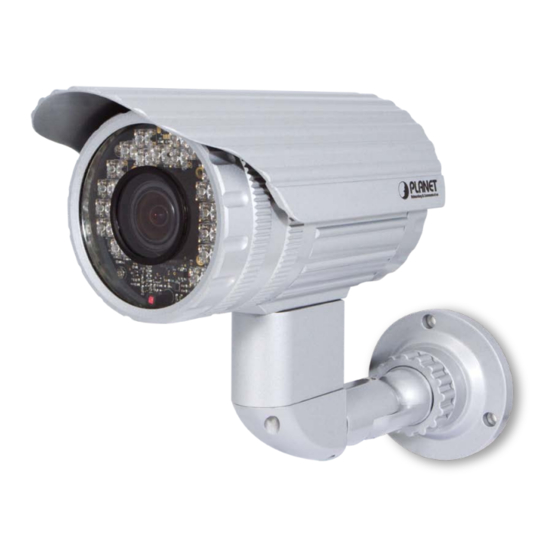
2.2 Physical Description 2.2.1 Identification of ICA-3350V physical detail Front View IR LEDs x 24 Lens Light sensor... -
Page 11: I/O Control Instruction
Item Description Lens set. Keep this area clean to keep excellent video quality. Lens Emits infrared light to provide light source in dark places IR LEDs Detects the illumination level or the place where this IP camera is installed, and switches IR LEDs on when it’s required. When IR LEDs are switched on, this IP camera will switch to black and white video mode to enhance video quality. - Page 12 Descriptions for I/O cable set: Interface Description Connects to your local area network by Ethernet cable LAN LED (green color) RJ45 LAN This LED will be flashing while network accessing via Ethernet socket Power LED (orange color) This LED is used to indicate whether DC power is on or not DC power input, connect to AC power adapter that supply the power to the Network Camera with the power Note:...
-
Page 13: Adjust Zoom/Focus Of Lens
2.2.3 Adjust zoom/focus of lens Focus stick Zoom stick 1. Open the back cover of the camera 2. Adjust zoom stick first 3. Adjust focus stick to get clear image 4. Close the back cover of the camera tightly. Otherwise, the camera may fail to waterproof. -
Page 14: Hardware Installation
2.3 Hardware Installation 1. Fix IR camera to desired location with stand Use three screws to fix the Network Camera onto the ceiling or wall. You could also put the Network Camera on the table directly. Fixed it by Screws 2. -
Page 15: Initial Utility Installation
If the welcome screen does not appear, click “Start” at the taskbar. Then, select NOTE: “Run” and type “D:\Utility\IPWizard II\setup.exe”, assume D is your CD-ROM drive. 3. The “Welcome to the InstallShield Wizard for PLANET IP Wizard II” prompt will display on the screen and click “Next” to continue. - Page 16 4. Please click “Next” to install with original settings, or you may click “Change…” button to modify the install folder then press “Next” to continue. 5. Please click “Install” to start the installation.
-
Page 17: Preparation
When you installed the Internet Camera on a LAN environment, you have two easy ways to search your cameras by PLANET IP Wizard II or UPnP discovery. Here is the way to execute PLANET IP Wizard II to discover camera’s IP address and set up related parameter in a camera. - Page 18 When launch the Planet IP Wizard II, a searching windows will pop up. Planet IP Wizard II is starting to search Internet Cameras on the LAN. The existed devices will be listed as below.
-
Page 19: Configure Network By Planet Ip Wizard Ii
View If Planet IP Wizard II finds Internet Camera, View button will be available. Please select the camera you want to view and click the View button. Then you could see the Video from camera directly. Furthermore you could double click the left button of mouse to link to the Internet Camera by browser. - Page 20 In case, you do not want to change username and/or password, then just click button to “Submit” perform your setting accordingly. Click button will go back to previous page. “<<” If you like to change username and/or password of the device, just click the check button. Then, the related fields will show up as below.
-
Page 21: Using Upnp Of Windows Xp Or Vista
2.6 Using UPnP of Windows XP or Vista 2.6.1 Windows XP UPnP™ is short for Universal Plug and Play, which is a networking architecture that provides compatibility among networking equipment, software, and peripherals. This device is an UPnP enabled device. If the operating system, Windows XP, of your PC is UPnP enabled, the device will be very easy to configure. - Page 22 The following screen will appear, select “Networking Services” and click “Details” to continue. The “Networking Services” will display on the screen, select “Universal Plug and Play” and click “OK” to continue.
- Page 23 Please click “Next” to continue. The program will start installing the UPnP automatically. You will see the below pop-up screen, please wait while Setup configures the components.
- Page 24 Please click “Finish” to complete the UPnP installation Double-click “My Network Places” on the desktop, the “My Network Places” will display on the screen and double-click the UPnP icon with Internet Camera to view your device in an internet browser.
-
Page 25: Windows Vista
ICA-3350V – 00304f0a145a 2.6.2 Windows Vista UPnP™ is short for Universal Plug and Play, which is a networking architecture that provides compatibility among networking equipment, software, and peripherals. This device is an UPnP enabled device. If the operating system, Windows Vista, of your PC is UPnP enabled, the device will be very easy to configure. -
Page 26: Windows 7
ICA-3350V – 00304fA15076 2.6.3 Windows 7 Go to Start > Control Panel > Network and Internet > Network and Sharing Center, if network discovery is off; click the arrow button to expand the section. Click Turn on network discovery, and then click Apply. -
Page 27: Setup Activex To Use The Internet Camera
2.7 Setup ActiveX to use the Internet Camera The Internet Camera web pages communicate with the Internet Camera using an ActiveX control. The ActiveX control must be downloaded from the Internet Camera and installed on your PC. Your Internet Explorer security settings must allow for the web page to work correctly. To use the Internet Camera, user must setup his IE browser as follows: 2.7.1. -
Page 28: Internet Explorer 7 For Windows Xp
By now, you have finished your entire PC configuration for Internet Camera. 2.7.2. Internet Explorer 7 for Windows XP From your IE browse ”Tools” ”Internet Options…” ”Security” ”Custom Level…”, please setup your “Settings” as follow. Set the first 3 items •... -
Page 29: Internet Explorer 7 For Windows Vista
By now, you have finished your entire PC configuration for Internet Camera. 2.7.3. Internet Explorer 7 for Windows Vista From your IE browse ”Tools” ”Internet Options…” ”Security” ”Internet” ”Custom Level…”, please setup your “Settings” as follow. • Enable “Automatic prompting for ActiveX controls” •... - Page 30 • Prompt “Initialize and script active controls not marked….” By now, you have finished your entire PC configuration for Internet Camera.
-
Page 31: Web-Based Management
The login window of Internet Camera will appear, Default login username/password is: admin / admin If the User name and Password have been changed with PLANET IP Wizard II, NOTE: please enter the new User name and Password here. After logged on, you should see the following messages at the top of Internet Explorer:... - Page 32 Click on the message, and click Install ActiveX Control… When you see this message, click Install’ to install required ActiveX control After the ActiveX control was installed and run, the first image will be displayed. You should be able to see the images captured from the Internet Camera in the web page now. For advanced functions, please refer to instructions given in follows chapters.
-
Page 33: Live View
3.3 Live View Start-up screen will be as follow no matter an ordinary users or an administrator. Video Profile ActiveX Control Streaming Protocol Language Monitor Image Section Setting Menu Client Setting Video Information 2-Way Audio Full Screen The image shot by the camera is shown here. The date and time are Monitor Image displayed at the top of the window. - Page 34 control within Microsoft® Internet Explorer. This function is detail setting for the camera that only available for Setting Menu user logged into camera as administrator. Item Action Configure Network settings such as Wireless, Network IPv6, ONVIF, DHCP, DDNS, 3GPP, PPPoE and UPnP.
-
Page 35: Activex Control
3.4 ActiveX Control The plug-in ActiveX control supports a lot of functions by clicking the left mouse button. Note that this feature only supports on the ActiveX control within Microsoft® Internet Explorer. On the ActiveX control icon, click the Left Mouse Button, then a menu pop-up. This menu provides features that are unique to the ActiveX control. -
Page 36: Record
3.4.2. Record Click Record to activate this function. Press Record button to start recording. The video file is saved as ASF format into your local PC. While you want to stop it, press Stop to stop recording. Select Browser, the pop-up window to select the save path and file name prefix, select OK to continue. -
Page 37: Volume
3.4.4. Volume Click Volume to activate this function. These have two control bars for speaker and microphone volume. Scroll this control bar to adjust the audio attribute. Check the volume mute will mute the speaker output. 3.4.5. About Click About to show the ActiveX information... -
Page 38: Network Configuration
3.5 Network Configuration Use this menu to configure the network to connect the device and the clients. 3.5.1. Network This section provides the menu of connecting the device through Ethernet cable. Display the Ethernet MAC address of the device. Note that user cannot MAC address change it. - Page 39 If you do not select “Obtain an IP address automatically”, then you need to enter these network parameters by yourself. This address is a unique numbers that identifies a computer or device on the WAN or LAN. These numbers are usually shown in groups IP Address separated by periods, for example: 192.168.0.200 Subnets allow network traffic between hosts to be separated based on...
-
Page 40: Ipv6
accessed from the WAN, then the HTTP Port can be assigned as the virtual server port mapping to support multiple devices. When the configuration is finish, please click “OK” to save and enable NOTE the setting. 3.5.2. IPv6 Internet Protocol version 6 (IPv6) is called the “IP Next Generation” (IPng), which is designed to fix the shortcomings of IPv4, such as data security and maximum number of user addresses. -
Page 41: Ddns Server
To enable or disable the HTTPS service here. Note that the HTTPS function of this device is not only encrypted the web content but also HTTPS audio/video data. Choose the HTTPS port. The default value is 443. Port 3.5.4 DDNS server Stands for Dynamic Domain Name Server The device supports DDNS If your device is connected to xDSL directly, you might need this feature. -
Page 42: Pppoe
To enable or disable the DDNS service here. DDNS Choose the built-in DDNS server. Server name The domain name is applied of this device. DDNS Host The user name is used to log into DDNS. User Name The password is used to log into DDNS. Password 3.5.5. -
Page 43: Streaming
To enable or disable the PPPoE service here. PPPoE Type the user name for the PPPoE service which is provided by ISP. User Name Type the password for the PPPoE service which is provided by ISP. Password Shows the IP information got from PPPoE server site. IP Address / Subnet Mask / Gateway Shows the Status of PPPoE connection. -
Page 44: Upnp
Choose the RTSP port. The RTSP protocol allows a connecting client to start a video stream. Enter the RTSP port number to use. The default value RTSP Port is 554. Specify the range of transmission port number of video stream. The default range is 50000 to 50999. -
Page 45: Bonjour
To enable or disable the UPnP service here. UPnP Shows the friendly name of this device here. Friendly Name When enabled, the device will attempt to configure port mapping in a NAT router on your network, using UPnP™. Note that UPnP™ UPnP NAT Traversal must be enabled in the NAT router first. -
Page 46: Onvif
To enable or disable the Bonjour service here. Bonjour Shows the friendly name of this device here. Friendly Name 3.5.9. ONVIF ONVIF is a global and open industry forum with the goal to facilitate the development and use of a global open standard for the interface of physical IP-based security products. -
Page 47: Ip Notification
To enable or disable the IP filter function here. IP Filter Choose the filter policy where is denying or allowing. IP Filter Policy 3.5.11. IP Notification In case the IP address is changed, system is able to send out an email to alert someone if the function is enabled. - Page 48 Type the server name or the IP address of the HTTP server Type the user name for the HTTP server. HTTP Login name Type the password for the HTTP server. HTTP Login Password Type the server name or the IP address of the HTTP Proxy. Proxy Address Set port number of Proxy.
-
Page 49: Camera Configuration
3.6 Camera Configuration Use this menu to set the function of the camera of Internet Camera 3.6.1. Picture Turn the “Mirror” and “Vertical Flip” On or OFF. The image will be overturned as below. Rotation Auto: will adjust the white balance automatically. White Balance Hold: will hold the white balance. - Page 50 Auto Exposure: will adjust the internal gain automatically. Hold Exposure: will hold the internal gain. Auto Iris: This Camera is built-in a DC-Iris lens. User can choose the Iris control mode from “Auto” or “Off”. In case, the “Auto” mode is selected, the Camera will control DC Iris automatically.
-
Page 51: Privacy Mask
parameters in advance: Night Mode Threshold (0~10000): this value set the threshold to turn on IR LED. It should be lower or equal to Day Mode Threshold. Day Mode Threshold (0~10000): this value set the threshold to turn off IR LED. It should be higher or equal to Night Mode Threshold. -
Page 52: Ptz Setting
To add or delete the privacy mask windows, user can specify up to 7 windows to mask the video captured by this device. By dragging Add and Delete mouse on the image, you can change the position and size of the selected window accordingly. -
Page 53: Preset Setting
3.6.4. Preset Setting This page provides the edit tool to modify or delete the “Preset Setting” item by item. 3.6.5. Tour Setting Up to 64 positions can be preset, and the camera can be programming to move to the preset position sequentially. - Page 54 The group name of the sequence of camera tour. The maximum number of Tour Name camera tour is 16. Enable or disable this camera tour. Running Set the sequence of the tour. Maximum 16 points can be assigned. The Preset selected preset position is added in the Sequence list from 1 to 16.
-
Page 55: System
3.7 System Use this menu to perform the principal settings of Internet Camera. 3.7.1. System You can enter the name of this unit here. It’s very useful to identify the Device title specific device from multiple units. This information shows the software version in the device. Software version Switch the LED light of this Internet Camera on or off, that Network LEDs will stop working;... -
Page 56: Date & Time
3.7.2. Date & Time User can setup the time setting of Internet Camera, make it synchronized with PC or remote NTP server. Also, you may select the correct time zone of your country. Displays the date and time of the device Server Date &... -
Page 57: Maintenance
Sets up the date and time of daylight saving stop time. Daylight Saving Stop Time Sets up the date of daylight saving offset. Daylight Saving Offset 3.7.3. Maintenance Recall the device hard factory default settings. Note that click Default Settings this button will reset all device’s parameters to the factory (Include the network settings (including the IP address). - Page 58 8. A message will be shown while the firmware upgraded. Once the upgrading process completed, the device will reboot the system automatically. 9. Please wait for 80 seconds, and then you can use PLANET IPWizard II to search the device again. Warning!!! The download firmware procedure cannot be interrupted.
-
Page 59: Video
3.8 Video This device provides 2 modes of video profile. The first one is 3Mega mode which supports video resolution up to 3 Mega-pixel. The second one is 2Mega mode which supports video resolution up to 2 Mega-pixel. User only can select either 3Mega or 2Mega mode to operate the camera. Switching 3Mega and 2Mega mode, the device will take time to reboot system. -
Page 60: Video Profile
Select your picture to upload Upload own image Select the location of the picture Coordinates 3.8.3. Video Profile User can modify the detail parameter for each video profiles in this page. -
Page 61: Roi
To assign a name to the selected profile. Name Video codec of the selected profile. Video Type Resolution of the selected profile. Resolution Assign the selected profile as a ROI stream or not. (Only available for the profiles with max resolution) Defines the rate control method of this profile. -
Page 62: Audio Configuration
3.9 Audio Configuration It’s M-JPEG mode in this profile. To enable or disable audio function. Audio To select G711 or G726 for audio coding. Audio type... - Page 63 To select Simplex or Full duplex (2-way audio) mode. Audio Mode: To adjust gain of input audio. Input Gain: To adjust gain of output audio. Output Gain: To enable or disable speaker function. Speaker Our...
-
Page 64: User Privilege Access Configuration
3.10 User Privilege Access Configuration Use this menu to set the user names and password of the Administrator and up to 10 users, and access right of each user. Select “Anonymous” to allow any one viewing the video once connected. Otherwise, only users in database can view the Viewer Login video after login. -
Page 65: E-Mail Configuration
3.11 E-Mail Configuration You may setup SMTP mail parameters for further operation of Event Schedule. That’s, if users want to send the alarm message out, it will need to configure parameters here and also add at least one event schedule to enable event triggering. Type the SMTP server name or the IP address of the SMTP server. -
Page 66: Object Detection
Type the subject/title of the e-mail. E-mail Subject 3.12 Object Detection Use this menu to specify motion detection window 1 to window 4 and set the conditions for detection while observing a captured image. To add or delete the motion windows. User can specify up to 4 Included and /or Excluded windows to monitor the video captured by Add and Delete this device. -
Page 67: Storage Configuration
3.13 Storage Configuration This page shows the status of attached SD card and Samba server. You may setup related parameters to manage the attached SD card or Samba server also. 3.13.1 SD Card This name of SD card. Disk ID This information of SD card. -
Page 68: Samba Server
3.13.2 SAMBA Server Type the server name or the IP address of the SAMBA server. Host Set working directory path of SAMBA server. Share Type the user name for the SAMBA server User Name Type the password for the SAMBA server. Password... -
Page 69: Continuous Recording
3.14 Continuous Recording You m ay enable or disable continuous recording function here. Select SD card or Samba server for storage destination. Note: When enable continuous recording that press restart will delete correct recording 3.15 Recording List iles list inside the SD Card This page shows the files list information, f . - Page 70 This page shows the files list information, files list inside the SD Card or Samba server. User may reload file from SD card or Samba server that play or remove the selected file.
-
Page 71: Event Server Configuration
3.16 Event Server Configuration 3.16.1 FTP Server You may setup FTP parameters for further operation of Event Schedule. That’s, if users want to send the alarm message to an FTP server, it will need to configure parameters here and also add at least one event schedule to enable event triggering as SMTP. -
Page 72: Tcp Server
3.16.2 TCP Server In addition to send video file to FTP server, the device also can send event message to specified TCP server. User can specify multiple TCP servers as wish. Therefore, user Name needs to specify a name for each TCP server setting. Type the server name or the IP address of the TCP server. -
Page 73: Http Server
3.16.3 HTTP Server The device also can send event message to specified HTTP server. User can specify multiple HTTP servers as wish. Therefore, user Name needs to specify a name for each HTTP server setting. Type the server name or the IP address of the HTTP server. Check the HTTP server whether it is available or not. -
Page 74: Samba Server
3.16.4 SAMBA Server The device also can send video stream to specified SAMBA server. Most of the time, the SAMBA server will be another PC or NAS server. User can specify multiple HTTP servers as wish. Therefore, user Name needs to specify a name for each HTTP server setting. Type the server name or the IP address of the SAMBA server. -
Page 75: Event Schedule Configuration
3.17 Event Schedule Configuration This menu is used to specify the schedule of Events and activate the some actions provided by this device. 3.17.1 Setting Name of the Event or Schedule. Name Enable or disable this Event or Schedule. Enable Schedule start with Event trigger or Schedule trigger. - Page 76 Example1. Send file to FTP server by motion triggered always: Select event trigger Enable time: start from 00:00 to 24:00 every day Trigger by: Motion Area (Added in Object Detection page) Action : Send FTP (Add in Event Server -> FTP Server page)
- Page 77 Example2. Send file to E-Mail server by motion triggered from Friday 18:00 to Saturday 06:00 Select event trigger. Enable time: start from Friday 18:00 and keep work in 12 hours, so it will stop on Saturday 06:00. Trigger by : Motion Area (Added in Object Detection page) Action : Send e-mail (Add in E-Mail page) To email address: You need to input the receiver email address.
- Page 78 Example3. Enable Voice Alert every 10-minute during 18:00 to 24:00 from Monday to Friday. 1. Type: Select schedule trigger and interval is 10-minute. 2. Enable Time: Select Monday to Friday, and set start time from 18:00 and keep work in 6 hours. 3.
-
Page 79: Record Configuration
3.17.2 Record Configuration User can choose the type of record file for event or schedule application. Choose AVI or JPEG file format for record file. Record File Type Define the prefix of recorded filename. Record File Prefix Define the maximum duration of pre-alarm. Pre-Trigger Duration Define the best effort duration of post-alarm. -
Page 80: Appendix A: Ping Ip Address
Appendix A: PING IP Address The PING (stands for Packet Internet Groper) command is used to detect whether a specific IP address is accessible by sending a packet to the specific address and waiting for a reply. It’s also a very useful tool to confirm Internet Camera installed or if the IP address conflicts with any other devices over the network. -
Page 81: Appendix B: 3Gpp Access
Appendix B: 3GPP Access To use the 3GPP function, in addition to previous section, you might need more information or configuration to make this function work. That to use the 3GPP function, it strongly recommends to install the Networked Device Note with a public and fixed IP address without any firewall protection. -
Page 82: Appendix C: Bandwidth And Video Size Estimation
Appendix C: Bandwidth and Video Size Estimation The frame rate of video transmitted from the Internet Camera depends on connection bandwidth between client and server, video resolution, codec type, and quality setting of server. Here is a guideline to help you roughly estimate the bandwidth requirements for your Internet Camera. The required bandwidth depends on content of video source. -
Page 83: Appendix D: Ddns Application
Appendix D: DDNS Application 1. Configure PLANET DDNS steps: Step 1: Enable DDNS option through accessing web page of NAS Step 2. Select on DDNS server provide, and register an account if you do not use yet. http://planetddns.com Let’s take dyndns.org as an example. Register an account in... -
Page 84: Appendix E: Configure Port Forwarding Manually
Manually setup the device with a fixed IP address, for example, 192.168.0.100. 2. Access the Router with Your Web browser The following steps generally apply to any router that you have on your network. The PLANET WNRT-620 is used as an example to clarify the configuration process. Configure the initial settings of the router by following the steps outlined in the router’s Quick Installation Guide. - Page 85 Your WAN IP Address will be listed here. 3. Open/set Virtual Server Ports to enable remote image viewing The firewall security features built into the router and most routers prevent users from accessing the video from the device over the Internet. The router connects to the Internet over a series of numbered ports.
- Page 86 Enter valid ports in the Virtual Server section of your router. Please make sure to check the box on this line to enable settings. Then the device can be access from WAN by the router’s WAN IP Address. By now, you have finished your entire PC configuration for this device.
-
Page 87: Appendix F: Power Line Frequency
Appendix F: Power Line Frequency COUNTRY VOLTAGE FREQUENCY COMMENTS *Neutral and line wires are reversed from that Argentina 220V 50 Hz used in Australia and elsewhere. *Outlets typically controlled by adjacent switch. Australia 230V* 50 Hz Though nominal voltage has been officially changed to 230V, 240V is within tolerances and commonly found. -
Page 88: Appendix G: Troubleshooting & Frequently Asked Questions
5 seconds on the device. 2. Reconfigure the device. Check IP address of device by using the PLANET IP Wizard II Forgot the IP address of the program or by UPnP discovery or set the device to default by Reset device. - Page 89 Do not connect device over a router. PLANET IP Wizard II program cannot detect device over a router. If IP address is not assigned to the PC which running PLANET IP Wizard II program, then PLANET IP Wizard II program cannot PLANET IP Wizard II program find device.
- Page 90 The port number assigned in your Internet Camera might not be available via Internet. Check your ISP for available port. The proxy server may prevent you from connecting directly to the Internet Camera, set up not to use the proxy server. Confirm that Default Gateway address is correct.
- Page 91 Check the bandwidth of Internet connection. If the Internet bandwidth is lower than target bit rate, the video streaming will not work correctly. Use the operating system of the selected language. Set the The unreadable characters are Encoding or the Character Set of the selected language on the displayed.
- Page 92 Windows Media Player 11.0 or later to play the AVI filed recorded by the Device. When stop continuous recording can’t run unmount SD card Can not unmount SD card immediately. Because of ICA-3350V series need about two immediately after stop continuous minutes to stop recording procedure. Please wait two minutes recording later then run unmount SD card.
-
Page 93: Appendix H: Product Specification
Appendix H: Product Specification ICA-3350V Product Camera 3 Mega-pixel Sony Exmor image sensor Image Sensor 1/2.8” Image Size Lens Vari-focal lens: f 3.0-9.0mm View Angle H: 40 ~ 97 degree V: 30 ~ 81 degree Effective Pixels 2048 x 1536 (QXGA) Min Illumination 0.5 lux @ F1.2... - Page 94 TCP/IP, UDP, HTTP, SMTP, FTP, NTP, DNS, DDNS, DHCP, DIPS ARP, Bonjour, UPnP, RTSP, RTP, RTCP, IGMP, PPPoE, 3GPP, ICMP, Network Protocol Samba Microsoft ® Internet Explorer 6.0 or later, PLANET Cam Viewer 3 Browser / Software Lite / Pro (CV3L . CV3P) 20 simultaneous unicast users...
- Page 95 RS485 Audio out External MIC input Composited video out Factory default reset 100 x 171mm Dimension (Φ x L) 940g Weight 10W (12VDC) Power Consumption -10 ~ 50 Degree C Operating Temperature 5 ~ 95% (non-condensing) Operating Humidity CE, FCC Emission...
Need help?
Do you have a question about the ICA-3350V and is the answer not in the manual?
Questions and answers