Table of Contents
Advertisement
Quick Links
Advertisement
Table of Contents

Related Manuals for Meyra FX One 1.150


Summary of Contents for Meyra FX One 1.150
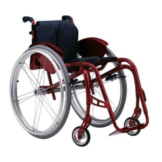
- Page 1 OPERATING MANUAL ACTIVE WHEELCHAIR, FX ONE Model 1.150 We move people.
-
Page 2: Table Of Contents
Contents Introduction ....................5 Acceptance ....................6 Adjustment ....................6 Handling the wheelchair ................6 Specifi cations ......................6 Use .........................7 Auxiliary drives .....................7 Overview ....................... 8 Driving ......................9 Safety information ....................9 Supplementary user/safety information .............9 Brake ......................11 Pressure Brake ....................12 Locking the pressure brakes .................12 Releasing the pressure brakes ..............12 Butterfl... - Page 3 Seat ......................19 Seat belt ......................19 Adjusting the seat depth ................19 Adjustment of seat inclination ..............19 Adjusting the seat height ................20 Back support ....................21 Folding over the back support ..............21 Folding up the back support ................21 Fitting the back belt ..................22 Adjusting the back support angle ...............23 Wheels ......................
- Page 4 Loading and transportation ..............32 Safety information ..................32 Transport in vehicles ..................32 Transport security ..................32 Safety information ..................33 Transport in handicapped transport automobile ..........34 Product liability instructions .................35 Safety information ..................35 Service ......................36 Cleaning and maintenance ................36 Upholstery and covers ..................36 Plastic parts ....................36 Finish ......................36 Chassis ......................37...
-
Page 5: Introduction
This operating manual is valid for way of a new styling of the proven model 1.150 with all equipment MEYRA technology. versions and accessories. It will With all equipment and their accesso- therefore contain sections that do ries the wheelchair offers die respec- not apply to your model. -
Page 6: Acceptance
ACCEPTANCE HANDLING THE WHEEL- CHAIR All products are checked for faults in the factory and packed in special Specifi cations boxes. The FX-one wheelchair, model 1.150 ☞ Note: was developed for adults and adoles- However, we request that you cents. Three frames are available: check the vehicle for possible transport damage immediately on –... -
Page 7: Use
Auxiliary drives Through its constructive advantages Before attaching auxiliary drives the the wheelchair can universally be following notes have to be consid- implemented on hard surfaces and ered: therefore an allround-wheelchair: Attention: – for indoors (e.g. apartment, day Attachment of auxiliary drives may care), only be done on wheelchair mod- els cleared for these. -
Page 8: Overview
OVERVIEW The overview shows the most important components of the wheelchair. ➀ ➀ Stabiliser brace – back support Backrest ➁ ➁ Arm support Arm support ➂ ➂ Handrims Seat belt/seat cushion ➃ ➃ Drive wheel Butterfl y-brake ➄ Footplate ➅ Steering wheel ➆... -
Page 9: Driving
DRIVING Supplementary user/safety information Alignment of the driving behaviour • Clean, passive lighting is required and the personal abilities is to be car- for driving in public traffi c. ried out together with your specialist • Do not throw or drop parts belong- dealer or therapist and is achieved af- ing to the wheelchair! –... - Page 10 • Never leave children/adolescents in • Tyres are made of a rubber mix- wheelchairs unsupervised. ture and can leave permanent or diffi cult-to-remove marks on some • Always approach small obstacles, surfaces (e.g. plastic, wooden or e.g. steps or curbs, slowly and at a parquet fl...
-
Page 11: Brake
BRAKE By locking the brakes the wheelchair is to secured against unintentional rolling off (parking brake). The locking brake belongs to the most important safety features of a wheel- chair and is available as a pressure brake (1) or butterfl y/brake (2). Attention: Please observe the maintenance instructions as well as instructions... -
Page 12: Pressure Brake
Pressure Brake A metered braking from driving speed (operating brake) is possible with the brake levers (1) of the pres- sure brakes. Service brake Press the two brake levers evenly only slightly to the front, this brakes the wheelchair in a metered fashion. Locking the pressure brakes To secure the wheelchair against any unintentional rolling, press both brake... -
Page 13: Butterfl Y-Brake
Butterfl y-Brake Locking the Butterfl y-brake To secure the wheelchair against any unintentional rolling, press both brake levers forward all the way (1). ☞ Note: It should not be possible to push the wheelchair forward when both brakes are locked. Releasing the Butterfl... -
Page 14: Foot Plate
FOOT PLATE A footplate is available (fi g. 1) that can be adjusted in height, angle and depth to the individual requirements. Adjusting the height of the footplate – Screw out the attachment screws (2) on both sides. – Position the footplate (1) accord- ingly in the desired height. -
Page 15: Adjusting The Angle Of The Footplates
Adjusting the angle of the foot- plates The footplate can be steplessly adjust- ed in angle. – Loosen the screws (3). – Press the footplate in to the de- sired angle. – In doing so observe the ground clearance. – Retighten the screws (3). Adjusting the depth of the foot- plates The footplate can be repositioned in... -
Page 16: Arm Supports
ARM SUPPORTS The arm supports (1) serve at the same time as arm support, clothes guard and wind guard. Attention: No not grab between the frame and arm support. – Danger of squashing! • Do not lift the wheelchair using the side elements. -
Page 17: Swivelling The Arm Support Inward
Swivelling the arm support in- ward The arm supports must be swivelled in front of the back support (4) in order to be folded forward (5). – Pull the arm support with a little pressure forward out of the brack- et (clamping mechanism) and swiv- el it inward in front of the back support (4). -
Page 18: Adjusting The Arm Support To The Wheel Circumference
Adjusting the arm support to the wheel circumference The distance X to the arm support running parallel to the wheel diame- ter (X) is to be aligned to the selected wheel position. Attention: The distance X between the driving wheel and the arm support should be as small as possible (approx. -
Page 19: Seat
SEAT Seat belt The seatbelt (1) is screwed onto the seat tubes. Adjusting the seat depth Attention: If an adjustment of the seat depth is necessary contact your specialist dealer. Adjustment of seat inclination The seat can be adjusted in angle. –... -
Page 20: Adjusting The Seat Height
Adjusting the seat height The seat height can be adjusted to the individual requirements. Front adjustment: – Dismantle the attachment screws (5) on each side. – Position the steering wheels par- allel according to the desired height. – Reassemble the attachment screws (5) on each side. -
Page 21: Back Support
BACK SUPPORT Folding over the back support The back support can be folded down for storage or transport. – For this swivel the arm supports in fi rst (1). – Disengage the back support by pulling or pressing the strap (2) at its centre and fold it onto the seat. -
Page 22: Fitting The Back Belt
Fitting the back belt The tension of the back support is ad- justable. – Pull the back belt off and fold it to the front (3). – Open the Velcro fastener of the belt that you wish to adjust and close it again after adjustment. -
Page 23: Adjusting The Back Support Angle
Adjusting the back support angle The angle of the backrest to the seat surface can be adjusted from +6° to - 18°. – Swivel up the arm support. – Loosen the counter nuts (5) of the stopper screws in the frame tube. –... -
Page 24: Wheels
WHEELS Drive wheels The driving wheels can be removed and reassembled without any tools. No person may be seated in the wheel- chair during assembly or removal. The wheelchair must stand on a level and fi rm surface. Before starting the dis- assembly work, support the frame to prevent the wheelchair from tipping over and secure it to prevent an un-... -
Page 25: Handrims
Handrims All handrims are designed for a dis- tance to the driving wheel of 15 mm (2), standard setting, and 25 mm. Attention: Replacement of handrims or modi- fi cation handrim distances should always be carried out by your specialist workshop. •... -
Page 26: Spoke Guard
Spoke guard The hand and spoke guard prevents injuries to the hands occurring by jamming in the turning spokes of the wheels, as well as damage to the spokes. – The spoke guard is attached to the spokes with three clips (3). ☞... -
Page 27: Centre Of Gravity
Centre of gravity The balance point is adjustable by re- positioning the axle tube. ☞ Note: The adjustment should be carried out by the specialist dealer! Attention: The overturning risk increases with a reduction in the axle separation distance (Forward displacement of the axle tube)! The axle tube must be displaced in a parallel manner for a perfect driving... -
Page 28: Wheel Camber
Wheel camber The wheel camber can be set to 1°, 3° or 6° by way of different axle mount adapters (2). ☞ Note: The adjustment should be carried out by the specialist dealer! Adjusting the wheel camber – Detach drive wheels. – Do this by pressing in the stop knob at the centre of the wheel and pulling off the wheel. -
Page 29: Toe-In
Toe-in The toe-in can be adjusted by rotating the mount adapter (2) for the axle. – Slightly loosen the clamping screws (3) of the tube clamp on each side. – It should be just possible to turn the axle mount adapter (2) with the open-end spanner. -
Page 30: Seat Belt
SEAT BELT The seatbelt serves to strap in a per- son sitting in the wheelchair. – Additional stabilisation of the sit- ting position. – Prevents the user from falling for- wards out of the wheelchair. – Continuous adjustment to suit the user’s needs. -
Page 31: Support Castor
SUPPORT CASTOR The support castor (1) serves to in- crease the tilting stability and can be swivelled upward (2). Attention: The support castor does not pro- vide suffi cient protection against tipping over in certain situations. Therefore, do not: ▲ Leaning the upper body far back. -
Page 32: Loading And Transportation
LOADING AND TRANS- Transport security Carry out the following steps when PORTATION the wheelchair is located in the trans- port vehicle: Safety information ▲ – Operate parking brakes. For the transport in vehicles, you must leave the wheelchair and sit –... -
Page 33: Safety Information
☞ Note: ☞ Suitable fi xing points can usually be found in the car and in the ve- hicle operating manual. ☞ Before transporting the wheelchair, ask your car dealer how to secure it without risk to the existing fi xtures or other safety fi... -
Page 34: Transport In Handicapped Transport Automobile
The power-knot-system is a fi rm, ret- Transport in handicapped rofi ttable element on the wheelchair, transport automobile on which the PRS and WRS merge. ☞ Note: These requirements are fulfi lled by a For transport in vehicles we recom- 4-point-system that consists of 2 front mend to leave the wheelchair and standardised latches for spanning re-... -
Page 35: Product Liability Instructions
☞ Safety information Note: ☞ The head support on the wheel- When transporting a person, make chair serves as a support for the sure that there are no objects posture of the head, not as a trans- jammed underneath the straps! port security. -
Page 36: Service
SERVICE Plastic parts The arm supports and parts are made Cleaning and maintenance of high-quality plastic. ☞ Only clean the plastic parts with ☞ Note: warm water and neutral detergent ☞ Do not clean the wheelchair with a or soft soap. high-pressure cleaner! Attention: ☞... -
Page 37: Chassis
Chassis Reinstallment The chassis and wheels can be cleaned Before reimplementation the wheel- damp with a mild detergent. After- chair is to undergo a complete inspec- wards dry off well. tion. ☞ ☞ Note: Note: Check the chassis for corrosion The measures required for reimple- damages as well as other damag- mentation are to be carried out in... -
Page 38: Flat Tyre
Flat tyre If a fl at tyre occurs to the air fi lled tyres due to puncture by sharp objects such as nails, screws, glass splinters, etc. the damage should be eliminated by repairing (mending the inner tube) or replacing the inner tube. Attention: Sitting in the wheelchair during a wheel change is not permitted. -
Page 39: Adjusting The Brakes
Adjusting the brakes According to the < Maintenance in- structions > the brakes are to be checked for function after each repo- sitioning of the drive wheels and re- adjusted if necessary. – Loosen the clamping screws (1) of a pressure resp. butterfl y-brake. –... -
Page 40: Maintenance
Maintenance Inspection The following maintenance Instruc- For safety reasons and to prevent ac- tions give you a guide for carrying out cidents which can result from wear the maintenance work. It does not out- not detected in good time, an annual line the actual scope of the necessary inspection is necessary in the case of work which can only be ascertained... -
Page 41: Maintenance Instructions
Maintenance instructions WHEN WHAT Remark Carry out test yourself or Before starting out Test brakes for fault- with a helper. less operation Activate brake lever to the limit. The locked wheels should not be able to turn under oper- ating conditions. If they can still turn, the brakes must be repaired by a specialist workshop. - Page 42 Maintenance instructions WHEN WHAT Remark Do it yourself or with the Before starting out Check air pressure of aid of a helper. the tyres For this use an air pres- Standard tyres: sure gauge or, if not 4 bar = 56 psi available conduct the High-pressure tyres: “thumb pressure meth-...
- Page 43 Maintenance instructions WHEN WHAT Remark Do it yourself or with the Every 8 weeks Lubricate the follow- aid of a helper. (depending on distance ing components with Components must covered) a few drops of oil free from used oil resi- –...
-
Page 44: List Of Annual Maintenance Work
List of annual maintenance work Preparation for visual check Remove the seat and back support elements, leg supports, arm support units. If necessary, clean the vehicle or the modules before the visual check. Visual check ❑ Check the frame, add-on components and accessories for damage, corrosion and damaged paintwork. -
Page 45: Repair
You must state the serial number (Fz-I- Repair Nr.) of the wheelchair when ordering To conduct repair or maintenance spare parts in order to ensure that the work trustfully contact a specialist correct spare part is supplied! You will workshop. It is briefed in carrying out fi... -
Page 46: Technical Data
TECHNICAL DATA All data within the following table relates to the standard version of the stated model. Dimensional tolerance is +/-1.5 cm, +/-2° Short form of wheelchair dimensions: SH = Seat height SW = Seat width SD = Seat depth BH = Backrest height Model: .................. - Page 47 Seat inclination adjustable: ..................... in steps of 1° Back support reclining Frame adjustable in steps of 3°: ..............+6° to -18° (The basic position of the back support is 90° to the not angled seat surface) Thigh length without seat cushion: ................38 to 51 cm Wheels Steering wheel Pneumatic tyres 6 x 1 ¼“: ..............
- Page 48 Weights Permissible total weight*: ..............max. 131 kg Max. permissible user weight (including additional load): ......120 kg maximum additional load: ................10 kg Empty weight: .................... min. 11 kg (with drive wheels) Seat cushion: ..................... 0.7 kg Transport weight: ..................min. 7.5 kg (without drive wheels) ☞...
-
Page 49: Tools
Tools The following tools are required for adjustments and maintenance: Open-end or ring spanner ......Wrench width (WW) 8 / 10 / 13 mm Hexagonal stud wrench ..........Wrench width 3 / 4 / 5 / 6 mm Phillips screwdriver .............. Size PH resp. PZ 0 / 1 / 2 Slot screw drivers .................. -
Page 50: Meaning Of The Labels On The Wheelchair
Meaning of the labels on the wheelchair Attention! Read the operating manuals and oth- er provided documentation. Do not lift the wheelchair at the arm supports or leg supports. Detachable parts are not suitable for carrying. Achtung Attention Bremse nachstellen. Readjust the brakes. -
Page 51: Notes
NOTES... - Page 52 NOTES...
- Page 53 NOTES...
-
Page 54: Guarantee
Guaranty is not granted for surface GUARANTEE damages, tyres of the wheels, dam- ages due to loosened screws or nuts We accept a guaranty for this prod- as well as worn out attachment holes uct according to the legal regulations. due to frequent assembly work. -
Page 55: Guarantee Coupon
GUARANTEE COUPON Fill in the details! If necessary, copy and return. Guarantee Model designation: Delivery note no.: Vehicle ID No. (Fz-I-Nr.) (view type Date of delivery: plate): Stamp of the dealer:... - Page 56 Your specialist dealer: MEYRA-ORTOPEDIA Vertriebsgesellschaft mbH Meyra-Ring 2 · D-32689 Kalletal-Kalldorf P.O. Box 1 703 • D-32591 Vlotho Fon +49 (0)5733 922-355 Fax +49 (0)5733 922-9355 info@meyra-ortopedia.de We move people. www.meyra-ortopedia.de 205 315 401 (Status: 2007-06) All technical modifi cations reserved!
Need help?
Do you have a question about the FX One 1.150 and is the answer not in the manual?
Questions and answers