Table of Contents
Advertisement
Advertisement
Table of Contents

Related Manuals for Meyra Optimus 2 2.322


Summary of Contents for Meyra Optimus 2 2.322
-
Page 1: Service Manual
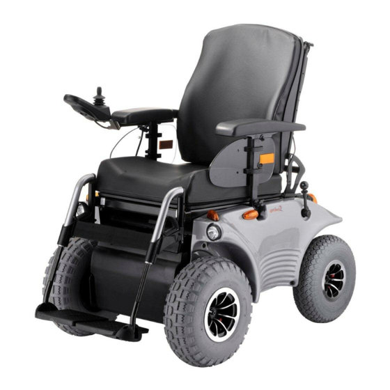
SERVICE MANUAL OPTIMUS 2, MODEL 2.322 TOURING 928, MODEL 9.928 move people. -
Page 3: Table Of Contents
Table of contents Foreword ..........................6 Requirements ..........................6 Vehicle identification ......................6 Overview ..........................6 Optimus 2 – Model 2.322 (2) ....................6 Touring 928 – Model 9.928 (3) ....................6 Drive unit ..........................7 Carbon brushes ..........................7 Removal ............................ - Page 4 Plug assignment ........................34 CAN-Bus software ......................... 35 Service program ........................35 Notes for loading new software into MEYRA-CAN modules: ..........39 Setting and changing the wheelchair type ................41 Driving programs ........................43 Programming with the operating module .................. 46 Adjustment modus ........................
- Page 5 Fuses ............................69 Main fuse ............................69 Electronic security ......................... 69 Maintenance/Servicing ......................70 Maintenance checklist ........................71 Electrical system ........................71 Mechanic ..........................72 DIN norms and guidelines ....................... 73 Notes ............................. 74...
-
Page 6: Foreword
Spare parts lists are sent out to you upon enquiry. All documents can also be downloaded from the fol- lowing site in the internet: < www.meyra.de >. REQUIREMENTS Special knowledge is required to carry out the mainte- nance work described in this service manual and may therefore only be carried out by educated qualified personnel. -
Page 7: Drive Unit
DRIVE UNIT The drive unit (1) consists of: – the motor, 24V-permanent magnet-direct current motor (A), – the magnetic brake, electro magnetic spring pres- sure brake (B) and – the maintenance free differential gear (C). CARBON BRUSHES When the motor is not running flawless and defects in the incoming lines can be excluded the four carbon brushes have to be checked one after the other. -
Page 8: Fitting
– Slightly pull out the carbon brush retainer (4). ☞ Note: Two opposite carbon brushes each are connected with each other through a cable (H) that runs over the motor. – Unscrew the phillips head screw (I) of the connec- tion cable. -
Page 9: Replacing The Drive Unit
REPLACING THE DRIVE UNIT The drive unit (1) can only be replaced as a complete driving unit (with the exception of the magnetic brakes). PREPARATIONS – Jack up the vehicle under the battery case so that the front wheels move freely. ☞... -
Page 10: Removal
REMOVAL – Unhook the bowden cable of the drum brake on both sides (3). – Unhook the bowden cable of the magnetic brakes (B) (4). – Dismantle the drum brake pads (5). ☞ Hereto observe chapter < Drum brake >. - Page 11 – Unscrew the 4 attachment screws (C) of the drive to the rocker on both sides. – Dismantle the screws of the shock absorber (D) on the side from which the rocker is to be removed. Remove the shock absorber. ☞...
-
Page 12: Mounting
MOUNTING The fitting is done analogue in reverse order. Attention: Secure the jointed bolt (E) of the rocker as well as the 4 attachment screws (C) of the drive to the rock- er on both sides with Loctite 243! ☞ Note: The cable harness has to be replaced carefully and attached to drive with cable binders. -
Page 13: Brakes
BRAKES ☞ Note: Switch the vehicle off in push mode. – This makes pushing the vehicle easier. The vehicle is fitted with a triple security system, con- sisting of: – The motor brake – an electro-magnetic spring pressure brake (magnetic brake). -
Page 14: Drum Brakes
DRUM BRAKES The two drum brakes for the drive wheels are activat- ed by the hand brake lever. ADJUSTING The drum brakes (A) are adjusted through the respec- tive bowden cable. – Jack up the vehicle. – Remove the panel on the side of the handbrake le- ver for the drum brake. -
Page 15: Replacing The Bowden Cable
REPLACING THE BOWDEN CABLE During replacement take care that the short bowden cable cover (C) runs from the lower adjustment screw (F) to the right brake arm (G) on right side use. For left hand operation it has to run from the lower adjustment screw to the left hand brake arm. -
Page 16: Magnetic Brake
MAGNETIC BRAKE The magnetic brake (A) is flanged to the motor (B). ☞ Note: Should the electro magnetic brake no longer hold the max. permitted total weight safely on a slope of 28% / 15°, the brake must be replaced. REMOVAL Disconnect the connector cable to remove the defec- tive electro magnetic brake. -
Page 17: Adjusting The Aeration Unit Of The Magnetic Brake And Steering Gear Disengage
ADJUSTING THE AERATION UNIT OF THE MAG- NETIC BRAKE AND STEERING GEAR DISENGAGE The adjustment is achieved through the bowden cable of the selection lever drive/push mode. 1. Jack up the vehicle. 2. Remove the side panel on the side of the selection lever drive/push mode. -
Page 18: Replacing The Bowden Cable
REPLACING THE BOWDEN CABLE – Jack up the vehicle. – Remove the side panel on the side of the selection lever drive/push mode as well as the front and rear revetment. ☞ Hereto observe chapter < revetment >. – Switch the selection lever drive- / push mode to drive mode. -
Page 19: Vehicle Suspension
VEHICLE SUSPENSION SUSPENSION OF THE CHASSIS For optimal sitting comfort the suspension (1) can be adjusted according to the desire of the user. Attention: Make sure that the adjustment ring sits securely before starting to drive. – Screw a loose adjustment ring tight enough, until the pressure of the spring prevents further loosen- ing. -
Page 20: Revetment
REVETMENT ATTACHING THE INSURANCE LICENSE PLATE – Position the insurance licence plate on the rear pan- el and use it as a drilling tableau in order to attach it. Then fasten the insurance license plate with suit- able attachment material (e. g. self-tapping screws B 4.2 x 9.5 mm or fillister head screws M 4 x 12 mm with self securing nuts) (A). -
Page 21: Attaching The Revetment Panels
ATTACHING THE REVETMENT PANELS Attaching the panel is achieved correspondingly in re- verse order to the removal. ☞ Note to rear panel: Check that the holding angle (7) is mounted under- neath the rear panel (A),with which the rear panel is attached to the steering gear. -
Page 22: Steering
STEERING As a standard the wheelchair is fit with electrical steer- ing (1) (completely mechanically operating steering optional). REPLACEMENT The steering unit (2) can be supplied completely as ex- change. REMOVAL – Set the steering lever (3) to drive mode. –... -
Page 23: Mounting
– Dismantle the nuts (7) of the angle joints (8). – Disconnect the steering gear from the frame. – Therefor unscrew the three attachment screws (9). MOUNTING ☞ Note: ☞ In the delivery condition the steering gear is tuned so that in the zero-position of the release director the gear rack is centred to the steering gear hous- ing. -
Page 24: Track And Straight Course
TRACK AND STRAIGHT COURSE ☞ Note: For adjustment to and inspection of the track the wheelchair is to be positioned on a level surface and loaded with about 100 kg on the seat. CHECKING THE ALIGNMENT – Switch the operating module on, put the joystick into the straight forward direction and let the wheel- chair drive a short distance. -
Page 25: Adjusting The Track And Straight Course
ADJUSTING THE TRACK AND STRAIGHT COURSE – Loosen the counter nuts (1) on both tie-rods left and right. – Switch the operating module on, put the joystick into the straight forward direction and let the wheelchair drive a short distance. –... -
Page 26: Replacing The Return Sensor
REPLACING THE RETURN SENSOR If the steering wheels, after releasing the joystick (zero position) do not align themselves in at least almost straight direction the return sensor (1) is to be replaced. ☞ Note: If the return sensor is exchanged it has to be com- pletely aligned again. - Page 27 Alignment of the return sensor: The return sensor can be aligned with the help of a slotted screw driver by tuning the potentiometer axle (5). ☞ The potentiometer axle can be reached from the bottom through a hole in the frame. ☞...
-
Page 28: Wheels
WHEELS ☞ The magnet for determining the speed is located inside the inner rim half of the steering wheels. As- sembly of the wheels does not depend on the side. WHEEL CHANGE Before starting the disassembly work, support the frame to prevent the wheelchair from tipping over and se- cure it to prevent an unwanted movement or tipping over. -
Page 29: Changing The Tyres
CHANGING THE TYRES Fully de-inflate the tyres for a tyre change. DISASSEMBLY OF THE TYRES 1. Disassemble the wheel. 2. Completely deflate the tyre. 3. Remove the red caps of the rim-half connection screws. 4. Unscrew the rim-half connection screws (B). ASSEMBLY OF THE TYRES Attention: During assembly the rim halves may not damage the... -
Page 30: Can-Bus Control
CAN-BUS CONTROL The CAN-Bus Control consists of the modules (those are the electronic hardware components) and the CAN-Bus Software. The CAN-Bus software is installed in the modules and controls the vehicle. Over the bus cable data is transferred between the modules of the vehicle (view diagram below). -
Page 31: Can-Bus Hardware
CAN-BUS HARDWARE The hardware of the CAN-Bus control consists of – Operating module – Power module – Adjustment module (option) The modules used for the CAN-bus control have – cables that are pluggable and secured against unin- tentional deletion (1), –... - Page 32 Magnetic key function C u s t o m e r The wheelchair can be locked with a magnetic key. For Service this magnetic key function must be enabled. This is the case directly from the manufacturer. The clearance can be done subsequently over the CAN-bus software.
-
Page 33: Plug Assignment
POWER MODULE The power module < PM >(3) stores the settings of the driving parameters and adopts as the power electronic the addressing of the driving- and steering motor re- spectively on two motor wheelchairs the addressing of both driving motors. The inlets and outlets of the power module are short circuit proof, so that the lead fuse is not applicable. -
Page 34: Adjustment Module
ADJUSTMENT MODULE When applying electric adjustment units the vehicle is equipped with an adjustment module < AM > (4) for addressing the adjustment motors. – The adjustment module is available in two different versions: – AM1 for 4 adjustment drives (back support, tilting, and two leg supports) –... -
Page 35: Can-Bus Software
Current software (updates) for the single CAN-bus modules is downloaded per internet from a Meyra- Homepage-Site and transferred to the respective mod- ule. The software version installed on the modules of a vehicle should always show the same version number. - Page 36 Operating system Precondition for the service program is one of the fol- lowing Microsoft operating systems: – Win 98 – Win ME – Win NT – Win 2000 – Win XP Functions of the service program The service program (2) is divided into the sections –...
- Page 37 External keyboards (1): – Setting the functions for external keys. Data record (2): – Current operating software (download of new wheelchair software to the wheelchair). – Setting the wheelchair type. – Basic settings (resets the parameters to the manu- facturer settings). –...
- Page 38 – Operating manuals stored on the PC can be viewed or printed. Special operations: – Information to special operations stored on the PC can be viewed or printed. – Tips & tricks. MEYRA-Homepage: – Direct link to the MEYRA-Homepage. About us: – Version number of the service programs.
-
Page 39: Notes For Loading New Software Into Meyra-Can Modules
If the above listed notes are not observed, new Before starting the following instructions are MEYRA-CAN modules may remain in an inop- to be read completely. If something is not clear erational state during the download. contact the MEYRA service department before... - Page 40 Therefore should the green LED beside – After the program is completed the MEYRA- the ‚Light’-key in the operating module only CAN modules should automatically return light up shortly and no other displays light up into a functioning state.
-
Page 41: Setting And Changing The Wheelchair Type
SETTING AND CHANGING THE WHEELCHAIR TYPE The type of wheelchair has to be defined since differ- ent motors and wheel sizes are applied and the stand- ard parameters have to be adapted. Setting the wheelchair type All power modules are supplied with a software ver- sion 10 or higher and are in the basic settings. - Page 42 Table 2: One-motor drive: Wheelchair type Display-entry Optimus hand steering 6 km/h Optimus 6 km/h Touring 927 6 km/h Touring 927 10 km/h Optimus hand steering 10 km/h Optimus 10 km/h Optimus 2 / Touring 928 6 km/h Optimus 2 / Touring 928 10 km/h Optimus 2 / Touring 928 12 km/h Optimus 2 / Touring 928 15 km/h 14 (version 13 and up)
-
Page 43: Driving Programs
DRIVING PROGRAMS The software installed on the power module contains five driving programs with different driving behaviour. You can for example call on separate programs for in- door and outdoor use. The user can change the driving behaviour of the wheelchair at any time by changing into a different driving program. - Page 44 Description of the programmable CAN-bus parameters 1. Forward final speed: The values 1 to 9 set the final speed forward, depend- ant on the maximum final speed of the wheelchair (6 or 10 km/h). 1 stands for minimum. 9 stands for maximum. 2.
- Page 45 6. Curve acceleration: The values 1 to 9 set the time that the steering set- point requires (joystick movement toward the right or left) in order to reach from zero to maximum value. This means the steering set-point is delayed through a run-up ramp.
-
Page 46: Programming With The Operating Module
PROGRAMMING WITH THE OPERATING MODULE The following functions can be amended directly through the operating module: – Adjustment of the parameters – Setting the joystick priorities – Selection of the special operation F H – Locking the program selection P1-P5 –... -
Page 47: Switching To The Adjustment Modus
SWITCHING TO THE ADJUSTMENT MODUS – Switch the wheelchair on. – Press the lower and the right service-key (2)+(3) si- multaneously and keep the pressed. – Additionally press the left service-key (1) and release it again. – This switches the wheelchair off. –... -
Page 48: Adjusting The Joystick Priority
ADJUSTING THE JOYSTICK PRIORITY – Activate the joystick-key (4). – The joystick-key LED light up and the display shows JPO. – Align the joystick in the desired priority sequence. – The joystick that is aligned first has the highest pri- ority. -
Page 49: Adjustment Of The Parameters
ADJUSTMENT OF THE PARAMETERS Selecting the driving program – Activate the P1-P5-key (5). – The P1-P5-key LED lights up. The LED for the program 1 < P1 > (10) lights up in the program number display for P1 to P5. ☞... -
Page 50: Concluding The Adjustment Modus
CONCLUDING THE ADJUSTMENT MODUS In order to conclude the adjustment modus and switch back into the driving modus the same keys are pressed in the same sequence as when starting the adjustment modus: – (While the vehicle is switched on:) Press the right and lower service key (2)+(3) simultaneously and keep them pressed. -
Page 51: Locking The Drive Program Selection
LOCKING THE DRIVE PROGRAM SELECTION Since some customers cannot cope with the possibility of selecting the driving programs P1 to P5 this possibil- ity can be locked over the operating module. Proceed as follows: 1. Switch on the wheelchair. 2. Select the program that should remain active with the mode key and activate it by moving the joystick. -
Page 52: Turning Special Mode F H On
TURNING SPECIAL MODE F H ON The special control mode makes it possible to use the joystick in place of the buttons. Proceed as follows: 1. Switch on the wheelchair. – Place the programming foil. 2. Press the right and lower service key (2)+(3) simulta- neously and keep them pressed. -
Page 53: Switching The Wheel Diameter On
SWITCHING THE WHEEL DIAMETER ON Proceed as follows: 1. Switch on the wheelchair. – Place the programming foil. 2. Press the right and lower service key (2)+(3) simulta- neously and keep them pressed. – Additionally press the left service-key (1) and release it again. -
Page 54: Setting The Speed Factor
SETTING THE SPEED FACTOR Setting the wheelchair type automatically sets every- thing and normally this setting fits if the components bought correspond with your declaration. Since the speed torque of the motors that are built into the Sprint or Champ can vary from your declaration, the final speed can be aligned over this factor. -
Page 55: Horn Signal Phase
HORN SIGNAL PHASE (The operating module without programming foil) The horn-signal can be switched on or off while giving a turn-signal or driving backwards. – Press and hold the minus-key (8). – Switch off the operating module. The change will become effective the next time the operating module is switched on. -
Page 56: Can-Bus Error List
CAN-BUS ERROR LIST Error- Type of Error Short-info to the cause Suggestion for Number trouble shooting E01/ E02 Watchdog error The watchdog-device of the oper- Replace defective bus- ating module has activated a re- cable, exchange oper- set. ating module. CAN- Bus- error The CAN module has switched into Replace defective bus-... - Page 57 CAN-BUS ERROR LIST PAGE 2 Error- Type of Error Short-info to the cause Suggestion for Number trouble shooting Dead-man-system er- Shortage in the dead-man-conduit Replace defective against +24V noted (PM). bus-cable, exchange operating module. CAN-Watchdog OM The operating module did not Replace defective send a Watchdog-message.
- Page 58 CAN-BUS ERROR LIST PAGE 3 Error- Type of Error Short-info to the cause Suggestion for Number trouble shooting Main relay error The relay is open even though it Exchange power should be closed. module. Magnetic brake error Failure (shortage or short cut) on Check magnetic the magnetic brake (PM1) or at...
- Page 59 Error on an adjustment motor Check adjustment justment module „1“ (shortage), adjustment motor not motor including the refit for MEYRA-CAN, error in the wiring, replace adjust- wiring to an adjustment motor. ment module. Motor shortage on ad- Error on an adjustment motor Check adjustment justment module „2“...
-
Page 60: Further Symbols
FURTHER SYMBOLS Symbol Meaning Info Remedy Brake release le- The traction drive is set to „push“: Move the brake release lever push the safety magnetic brake is me- to drive mode. mode activated chanically aired, the wheelchair is electrically blocked. OPTIMUS: Brake release lever at the front on the gear box cover. -
Page 61: Replacing The Can-Bus Modules
REPLACING THE CAN-BUS MODULES The power module (A) is screwed from the back onto the rear wall of the battery case. An optional adjustment module (B) is located on the bottom of the seat shell. REPLACEMENT OF THE POWER- AND ADJUST- MENT MODULE –... -
Page 62: Replacement Of The Operating Module
REPLACEMENT OF THE OPERATING MODULE REMOVE THE OPERATING MODULE – With the locking device bolt (A) depressed, swivel the cable protection down (B). – Press the plug latch (C) and pull the plug. – Loosen the clamping screw (D) of the bracket and pull the operating out toward the front. -
Page 63: Lighting
LIGHTING The lighting equipment must the checked regularly for function. REPLACING A LIGHTBULB ☞ Note: If a turn-signal bulb is defective, the remaining one blinks at double frequency. Replacing the bulb of the headlight Removal (Touring 928, model 9.928): – Pull the headlight out to the front out of the brack- et (1). -
Page 64: Adjusting The Headlights
Removal (Optimus 2, model 2.322): – Pull the headlight insert (A) toward the front out of the housing (B). – Turn the bayonet catch by about 15° counter-clock- wise (2) and pull (3). – Keep hold of the headlight insert in order to prevent it from turning along. –... - Page 65 Lighting components with dispersion disc: – Disassemble the dispersion disc from the affected lighting component. – To achieve this unscrew the attachment screw(s) and remove the dispersion plate. – Replace the defective light bulb. – Remount the dispersion plate. Attention: Watch for the correct voltage of the replacement bulb! Filament bulbs:...
-
Page 66: Batteries
BATTERIES CHARGE Attention: Deep discharge very quickly leads to capacity loss. – Therefore the batteries have to be charged at once (1). Especially before a longer storage the batteries are to be completely charged and because of the constant own discharge to be recharged in-between. Marginally increased transition resistance (>... -
Page 67: Types Of Batteries
Furthermore the maximal capacity sinks very rapidly in starter batteries. Even though the acquisi- tion costs are higher the use of traction batteries is more economical. ☞ Note: Only use batteries released by Meyra-Ortopedia when replacing old batteries. -
Page 68: Maintenance Of Liquid Batteries
MAINTENANCE OF LIQUID BATTERIES Power batteries that are cyclically strained need to be charged above the gas dimerisation due to the demand for short charging cycles and the necessary acid blend- ing. This means water consumption by water disrup- tion that must be balanced through regular refills. For refilling only use distilled water. -
Page 69: Fuses
FUSES MAIN FUSE The main fuse is switched in line in-between the two batteries. The main fuse holder (A) is located underneath the seat, on top of the batteries. ELECTRONIC SECURITY All electrical components (except for the batteries) are electronically protected by the power module (B). The power module also sees to a power limitation of the motors. -
Page 70: Maintenance/Servicing
We move people. MAINTENANCE/SERVIC- Wheelchairs are medical devices of the class I- MDD. As a medical device they underlie the operator provision and are to be maintained regularly. We recommend at least once a year. The work done and replacement of essential parts is to be documented. -
Page 71: Maintenance Checklist
MAINTENANCE CHECKLIST ELECTRICAL SYSTEM Batteries ❑ No external damage or stains on the batteries? ❑ Attachment cables tight on the battery contacts? ❑ Poles and attachment clamps cleaned and greased with Vaseline or Acid protector grease? ❑ Operation capability of the batteries ensured (capacity check)? ❑... -
Page 72: Mechanic
MAINTENANCE CHECKLIST Driving ❑ Test drive done? ❑ Personal barriers of the user regarded during the adjustment of the driving features? ❑ Variation from the adjusted maximum speed not more than + 10 % on level surface? ❑ Vehicle drives straight with straight setting of the joystick? ❑... -
Page 73: Din Norms And Guidelines
50 Nm Loctite 243 (medium hard) ... 205 638 800 M 12 85 Nm MEYRA-ORTOPEDIA Vertriebsgesellschaft mbH Meyra-Ring 2 · D-32689 Kalletal-Kalldorf P.O. Box 1 703 • D-32591 Vlotho 05733 922-355 05733 922-9355 info@meyra.de · www.meyra.de info@ortopedia.de · www.ortopedia.de We move people. -
Page 74: Notes
NOTES... - Page 75 NOTES...
- Page 76 Your specialist dealer: MEYRA-ORTOPEDIA Vertriebsgesellschaft mbH Meyra-Ring 2 · D-32689 Kalletal-Kalldorf P.O. Box 1 703 • D-32591 Vlotho +49 (0)5733 922-355 +49 (0)5733 922-9355 info@meyra.de · www.meyra.de move people. info@ortopedia.de · www.ortopedia.de 205 315 101 (Status: 2006-09) All technical modifi cations reserved!
Need help?
Do you have a question about the Optimus 2 2.322 and is the answer not in the manual?
Questions and answers