Table of Contents
Advertisement
Quick Links
Advertisement
Table of Contents

Subscribe to Our Youtube Channel
Related Manuals for Meyra MEX-X 1.130


Summary of Contents for Meyra MEX-X 1.130
- Page 1 OPERATING MANUAL MEX-X, MODEL 1.130 MEX-S, MODEL 1.134 We move people.
-
Page 2: Table Of Contents
Contents Introduction ....................5 Acceptance ....................6 Adjustment ....................6 Handling the wheelchair ................6 Specifi cations ......................6 Use .........................7 Auxiliary drives .....................7 Driving ........................7 Overview ....................... 8 Model 1.130, Mex-x ..................8 Model 1.134, Mex-s ..................9 Folding/Transport ..................10 Folding/Unfolding ....................10 Folding the wheelchair .................10 Carrying the wheelchair ................11 Unfolding the wheelchair ................11... - Page 3 Arm supports ....................21 Adjusting the arm support to the wheel circumference ......21 Arm support ....................22 Back support ....................23 Adjustable back .....................23 Angle adjustable back support code 29 ............24 Height adjustable push handles code 502 ............25 Removing the push handles .................26 Inserting the push handles ................26 Stabiliser rod .......................27 Removing/attaching the stabiliser rod ............27...
- Page 4 Support wheels ..................35 Swivel-away support castors ................35 Swinging the support castors ...............35 Stick-in support wheels ..................36 Removing/attaching the support castor ............36 Adjusting the support castor ...............36 Correct support castors length ..............36 Service ......................37 Cleaning and maintenance ................37 Upholstery and covers ..................37 Plastic parts ....................37 Finish ......................37 Chassis ......................38...
-
Page 5: Introduction
We have therefore also listed chapters styling of the proven MEYRA technol- with options that might not be appli- ogy. cable for your vehicle. -
Page 6: Acceptance
ACCEPTANCE HANDLING THE WHEEL- CHAIR All products are checked for faults in the factory and packed in special Specifi cations boxes. The wheelchairs of the Mex series ☞ Note: were developed for children and However, we request that you youngsters. Two frames are avail- check the vehicle for possible able: transport damage immediately on... -
Page 7: Use
Auxiliary drives Through its constructive advantages Before attaching auxiliary drives the the wheelchair can universally be following notes have to be consid- implemented on hard surfaces and ered: therefore an allround-wheelchair: Attention: – for indoors (e.g. apartment, day Attachment of auxiliary drives may care), only be done on wheelchair mod- els cleared for these. -
Page 8: Overview
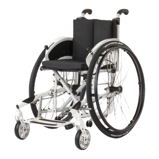
OVERVIEW Model 1.130, Mex-x The overview shows the most important components of the wheelchair. 8 Push handle 1 Back support 9 Pressure brakes 2 Side element 10 Handrims 3 Seat belt/seat cushion 11 Support wheel 4 Footplate Steering wheel Drive wheel 7 Quick release axle... -
Page 9: Model 1.134, Mex-S
Model 1.134, Mex-s The overview shows the most important components of the wheelchair. 8 Push handle 1 Back support 9 Pressure brakes 2 Side element 10 Handrims 3 Seat belt/seat cushion 11 Support wheel 4 Footplate Steering wheel Drive wheel 7 Quick release axle... -
Page 10: Folding/Transport
FOLDING/TRANSPORT Folding/Unfolding ☞ Only on model 1.130 Folding the wheelchair Your wheelchair can be folded in a few moments without tools being re- quired (1) – Remove the seat cushion, if appli- cable. – Folding up the footboard, view chapter < Footboard >. –... -
Page 11: Carrying The Wheelchair
Carrying the wheelchair Your wheelchair can be carried with- out diffi culty when folded. Fold the wheelchair, therefore view chapter < Folding the wheelchair >. From the front push one lower arm under the upward folded seat belt. Place other hand underneath the rear seat fold for support. -
Page 12: Brake
BRAKE By locking the brakes with the brake lever (1), the wheelchair is secured against rolling away unintentionally (parking brake). The locking brake belongs to the most important safety features of a wheel- chair and is available as a pressure brake (2). -
Page 13: Pressure Brake
Pressure Brake Locking the pressure brakes To secure the wheelchair against any unintentional rolling, press both brake levers forward all the way (1). ☞ Note: It should not be possible to push the wheelchair forward when both brakes are locked. Releasing the pressure brakes Pull both brake levers back all the way (2). -
Page 14: Drum Brake For Attendant
Drum brake for attendant A metered braking from driving speed (operating brake) is possible with the brake levers of the drum brakes. The wheelchair is also to be secured against unintentionally rolling away (parking brake) by engaging these brakes. Locking the drum brakes Pull both brake levers evenly to secure the wheelchair against unintentional rolling away. - Page 15 Loosen the drum brakes Pull both brake levers (1) until the latches (2) automatically jump out of the lock. Release both brake levers. – The park- ing brakes are release and the wheel- chair ready to go. Attention: For driving the front and rear brake levers must be disengaged.
-
Page 16: Foot Board
FOOT BOARD Footboards (1) are available that can be adjusted in height, angle and depth to the individual requirements. Folding up the foot board For an unobstructed foot area, fold up the left side of the foot board to the right as far as it will go (2). Folding down the foot board Fold down the left side of the foot board holder until it rests on the foot... -
Page 17: Adjusting The Angle Of The Footboard
Adjusting the angle of the foot- board The footboard can be adjusted by one position in both directions in angle. – Screw out the attachment screws (1) on both sides. – Swivel the footboard tubes (2) par- allel into the desired angle. –... -
Page 18: Folding Footboard
Folding footboard Folding the footboard The footboard (1) can be folded to- ward the rear and up (2) to achieve more space for the feet. Folding down the foot board Swivel the footboard down as far as possible (1). Adjusting the height of the foot- board –... -
Page 19: Adjusting The Angle Of The Footboard
Adjusting the angle of the foot- board The footboard can be adjusted by two positions each in both directions and angle (1)+(2). – Screw out the attachment screws (3) on both sides. ☞ Note: Watch for loose parts such as nuts and washers! –... -
Page 20: Depth Adapter
Depth adapter The footboard is placed further to- ward the front by inserting the depth adapters (1) on both sides. – Screw out the attachment screws (2) on both sides. – Insert the depth adapters and mount them with the screws (2). –... -
Page 21: Arm Supports
ARM SUPPORTS The arm supports (1) serve at the same time as arm support, clothes guard and wind guard. Attention: Do not grab between the seat and back tubes and arm supports. – Danger of squashing! • Do not lift the wheelchair using the side elements. -
Page 22: Arm Support
ARM SUPPORT Swivel up the arm supports The arm supports (1) can be swivelled upward (2) when necessary. Swivelling down the arm sup- ports When swivelling down the arm sup- port the collar of the stopper should glide into the groove of the arm sup- port tube (3). -
Page 23: Back Support
BACK SUPPORT Adjustable back The adjustable back is adjustable through a velcro strap, the so called spanning straps (2). The cushion (1) is placed over it and attached with the velcro strap (3). ☞ Note: ☞ Adjustment of the adjustable back strap (2) is best achieved while the user is sitting inside the wheel- chair. -
Page 24: Angle Adjustable Back Support Code 29
Angle adjustable back sup- port code 29 The back support is adjustable by max. +/– 15° in three steps of 5° each (1)+(2). – Loosen the attachment screws (3) on both sides. ☞ Priorly remove the drive wheel in order to loosen the screw of the left back support tube. -
Page 25: Height Adjustable Push Handles Code 502
Height adjustable push han- dles code 502 The push handles (1) are steplessly height adjustable and secured against pulling out. Height adjustment – Secure the pushing handle with one hand against unintentionally falling down. – Swivel the locking lever (2) up with one hand (3) until the respective pushing handle can be adjusted. -
Page 26: Removing The Push Handles
Removing the push handles – Secure the pushing handle with one hand against unintentionally falling down. – Swivel the locking lever (2) up with one hand (3) until the respective pushing handle can be adjusted. – Pull the pushing handle up as far as possible. -
Page 27: Stabiliser Rod
Stabiliser rod The stabiliser rod (1) stretches the back strap at the top, serves to attach the head support and is secured against being pulled out. ☞ Note: Only in combination with height ad- justable push handles The stabiliser rod can be removed in order to fold the wheelchair. -
Page 28: Head Support
HEAD SUPPORT The headrest (1) is swivel proof, height adjustable and removable. Adjustment of the head support ☞ Note: After inserting/adjusting the head support, the respective are to be retightened. Height adjustment / removal For height adjustment and removal of the head support loosen the clamping screw (2). -
Page 29: Wheels
WHEELS Drive wheels The driving wheels can be removed and reassembled without any tools. No person may be seated in the wheel- chair during assembly or removal. The wheelchair must stand on a level and fi rm surface. Before starting the dis- assembly work, support the frame to prevent the wheelchair from tipping over and secure it to prevent an un-... -
Page 30: Handrims
Handrims All handrims are designed for a dis- tance to the driving wheel of 15 mm (2), standard setting, and 25 mm. Attention: Replacement of handrims or modi- fi cation handrim distances should always be carried out by your specialist workshop. -
Page 31: Hand And Spoke Guard
Hand and spoke guard The hand and spoke guard prevents injuries to the hands occurring by jamming in the turning spokes of the wheels, as well as damage to the spokes. – The spoke guard is attached to the spokes with three clips (3). ☞... -
Page 32: Settings
SETTINGS If necessary the following adjustments can be made retrospectively for the user: – the seat depth, – the front seat height (1), – the rear seat height (2), – the seat angle, – the axle distance (balance point), – the lower shank length (3). ☞... -
Page 33: Wheel Camber
Wheel camber The wheel camber can be set to 3°, 6° or 9° by way of different axle mount adapters (5). ☞ Note: Assembly should be carried out in a suitable specialist workshop! Adjusting the wheel camber 1. Detach the drive wheels. ☞... -
Page 34: Seat Belt
SEAT BELT The seatbelt serves to strap in a per- son sitting in the wheelchair. – Additional stabilisation of the sit- ting position. – Prevents the user from falling for- wards out of the wheelchair. – Continuous adjustment to suit the user’s needs. -
Page 35: Support Wheels
SUPPORT WHEELS The support castors serve to increase the tilting stability. Attention: In certain situation the support castors do not provide suffi cient protection against falling over. Therefore, do not: ▲ Leaning the upper body far back. ▲ When the wheelchair starts sud- denly, especially when driving up- hill. -
Page 36: Stick-In Support Wheels
Stick-in support wheels Removing/attaching the support castor Press the respective spring button (4) in order to remove (1) / insert (2)+(3) the support castors. When replacing the support castors (2)+(3) slide them in until the spring button automatically snaps into place. -
Page 37: Service
SERVICE Plastic parts The arm supports and parts are made Cleaning and maintenance of high-quality plastic. ☞ Only clean the plastic parts with ☞ Note: warm water and neutral detergent ☞ Do not clean the wheelchair with a or soft soap. high-pressure cleaner! Attention: ☞... -
Page 38: Chassis
Chassis Reinstallment The chassis and wheels can be cleaned Before reimplementation the wheel- damp with a mild detergent. After- chair is to undergo a complete inspec- wards dry off well. tion. ☞ ☞ Note: Note: Check the chassis for corrosion The hygienic measures required damages as well as other damag- for reimplementation are to be... -
Page 39: Maintenance Schedule
Maintenance schedule WHEN WHAT Remark Carry out test yourself or Before starting out Test brakes for fault- with a helper. less operation Activate brake lever to the limit. The locked wheels should not be able to turn under oper- ating conditions. If they can still turn, the brakes must be repaired by a specialist workshop. - Page 40 Maintenance schedule WHEN WHAT Remark Do it yourself or with the Before starting out Check air pressure of aid of a helper. the tyres Use a tyre pressure tester Standard tyres: or, if not available, the 4 bar = 56 psi 'thumb press' method or High-pressure tyres: similar (view Safety in-...
- Page 41 Maintenance schedule WHEN WHAT Remark Do it yourself or with the Every 8 weeks Lubricate the follow- aid of a helper. (depending on distance ing components with Components must covered) a few drops of oil free from used oil resi- –...
-
Page 42: Flat Tyre
Flat tyre If a fl at tyre occurs to the air fi lled tyres due to puncture by sharp objects such as nails, screws, glass splinters, etc. the damage should be eliminated by repairing (mending the inner tube) or replacing the inner tube. Attention: Sitting in the wheelchair during a wheel change is not permitted. -
Page 43: Adjusting The Brakes
Adjusting the brakes The brakes are to be checked for func- tion according to the < Maintenance schedule > as well as after each reposi- tioning of the drive wheels and read- justed if necessary. Pressure brake: 1. Loosen the counter nut (2). 2. -
Page 44: Repositioning The Brakes
Repositioning the brakes After each repositioning of the drive wheels (wheel base extension) both brakes are to be checked for function and repositioned if necessary. ☞ Note: Repositioning of the brakes as well as the required adjustment should be carried out by the specialist dealer! 1. -
Page 45: Adjusting The Drum Brake
Adjusting the drum brake 1. First loosen the counternut (2) in order to adjust the or readjust the drum brake (1). 2. Then screw out the adjustment screw (3) for tuning. 3. Afterwards retighten the counter nut. ☞ Note: The wheelchair loaded with a per- son may no longer let itself be pushed with activated brakes (sec- ond engage position, view chapter... -
Page 46: Repair
You must state the serial number (Fz-I- Repair Nr.) of the wheelchair when ordering To conduct repair or maintenance spare parts in order to ensure that the work trustfully contact a specialist correct spare part is supplied! You will workshop. It is briefed in carrying out fi... -
Page 47: Inspection
INSPECTION For safety reasons and to prevent ac- cidents which can result from wear not detected in good time, an annual inspection is necessary in the case of normal operating conditions. This is to be carried out in accordance with the following service checklist. -
Page 48: List Of Annual Maintenance Work
List of annual maintenance work Preparation for visual check Remove the seat cushion and back cushion. If necessary, clean the vehicle or the modules before the visual check. Visual check ❑ Check the frame, add-on components and accessories for damage, corrosion and damaged paintwork. -
Page 49: Inspection Certifi Cate Through The Dealer
Inspection certifi cate through the dealer Vehicle data: Model: Delivery note no.: Vehicle identifi cation No. Recommended safety inspection (at least every 12 months) Pre-delivery inspection Stamp of specialist dealer: Stamp of specialist dealer: Signature: Signature: Place, date: Place, date: Next safety inspection in 12 months Next safety inspection in 12 months Date:... - Page 50 Recommended safety inspection Recommended safety inspection (at least every 12 months) (at least every 12 months) Stamp of specialist dealer: Stamp of specialist dealer: Signature: Signature: Place, date: Place, date: Next safety inspection in 12 months Next safety inspection in 12 months Date: Date: Recommended safety inspection...
-
Page 51: Technical Data
SW = Seat width SD = Seat depth BH = Backrest height RSH = Rear seat height Model: ..............MEX-X 1.130, MEX-S 1.134 Type plate: ................at the crossbrace tube Two frames are available: – MIDI (only with 20" and 22") –... - Page 52 Seat cushion thickness: ...................3 / 6 cm Seat inclination adjustable: .....................0° / 3° / 6° / 9° Thigh length without seat cushion: ................14 to 38 cm Height of push-handles: Code 502 (steplessly adjustable): ..............20 cm Wheels Steering wheel 4“, resp. Ø 100 mm: ................solid rubber 5“, resp.
- Page 53 Weights Permissible total weight*: ............... max. 85 kg Max. permissible user weight (including additional load): ......75 kg maximum additional load: ................10 kg Empty weight: .................... min. 10 kg (with drive wheels) Seat cushion: ..................... 0.7 kg Transport weight: ..................min. 7.5 kg (without drive wheels) ☞...
-
Page 54: Tools
Tools The following tools are required for adjustments and maintenance: Open-end or ring spanner ......Wrench width (WW) 8 / 10 / 13 mm Hexagonal stud wrench ..........Wrench width 3 / 4 / 5 / 6 mm Phillips screwdriver .............. Size PH resp. PZ 0 / 1 / 2 Slot screw drivers .................. -
Page 55: Meaning Of The Labels On The Wheelchair
Meaning of the labels on the wheelchair Attention! Read the operating manuals and oth- er provided documentation. Do not lift the wheelchair at the arm supports or leg supports. Detachable parts are not suitable for carrying. Attention Readjust the brakes. Attention Increased danger of tilting when on inclinations / slopes, especially in com-... -
Page 56: Notes
NOTES... - Page 57 NOTES...
-
Page 58: Guarantee
Guaranty is not granted for surface GUARANTEE damages, tyres of the wheels, dam- ages due to loosened screws or nuts We accept a guaranty for this prod- as well as worn out attachment holes uct according to the legal regulations. due to frequent assembly work. -
Page 59: Guarantee Coupon
GUARANTEE COUPON Fill in the details! If necessary, copy and return. Guarantee Model designation: Delivery note no.: Vehicle ID No. (Fz-I-Nr.) (view type plate): Date of delivery: Stamp of the dealer:... - Page 60 Your specialist dealer: MEYRA-ORTOPEDIA Vertriebsgesellschaft mbH Meyra-Ring 2 · D-32689 Kalletal-Kalldorf P.O. Box 1 703 • D-32591 Vlotho Fon +49 (0)5733 922-355 Fax +49 (0)5733 922-9355 info@meyra-ortopedia.de We move people. www.meyra-ortopedia.de 205 325 301 (Status: 2007-09) All technical modifi cations reserved!
Need help?
Do you have a question about the MEX-X 1.130 and is the answer not in the manual?
Questions and answers