Table of Contents
Advertisement
Quick Links
Advertisement
Table of Contents

Related Manuals for Meyra Oprtimus 2


Summary of Contents for Meyra Oprtimus 2
- Page 1 Optimus 2 / - 2S Model 2.322 Operating manual W e m o v e p e o p l e .
-
Page 2: Table Of Contents
Contents Meaning of the applied markers Introduction List of models Indications Acceptance Specifications Adjustment Reinstallment Life span Statutory regulations Insurance licence plate High-frequency radiation Overview Model: 2.322 Handling the electric wheelchair Securing the electric wheelchair Functional checks Driving Brakes Service brake Braking the electric wheelchair Emergency braking Drum Brake... - Page 3 Positioning the operating module Function description Adjusting the distance to the padded arm support Removing the operating module Inserting the operating module Swivelling the operating module Height adjustment of the operating module Leg supports Calf belt Removing the calf belt Attaching the calf belt Length adjustment of the calf belt Lower leg support...
- Page 4 Ergo Seat Folding over the back support Folding up the back support Adjusting the back support angle Electrically adjustable back support Folding down the electrically adjustable back support Unfolding the back support Lap belt Strapping on the lap belt with lock Adjustment of belt length Head support Seating system ERGO Seat...
- Page 5 Basic safety information Transfer out of the electric wheelchair Driving on falling, rising or transverse gradients Crossing obstacles Driving on public highways Service Tyres Cleaning and maintenance Upholstery and covers Disinfection Reinstallment Repairs Customer Service Spare parts Disposal Technical data Maximum range Hill climbing ability Values acc.
-
Page 6: Meaning Of The Applied Markers
< Informa- tion center > on our website: Safety instructions with a coloured back- < www.meyra.com >. ground are mandatory and need to be observed under any circumstance! Our implemented assembly groups and components fulfil the demands of the ☞... -
Page 7: Acceptance
ACCEPTANCE In certain configurations your electric wheelchair might exceed the maximum All products are checked for faults in the dimensions of emergency routes. factory and packed in special boxes. ☞ However, we request that you check Always make sure whether possible es- the vehicle for possible transport dam- cape routes are wide enough for your age immediately on receipt –... -
Page 8: Adjustment
ADJUSTMENT LIFE SPAN We expect an average life span of about Always have adaptation and adjustment 5 years for this product, as far as the product work carried out by a specialist dealer. is applied for its designated purpose and all The electric wheelchair offers manifold maintenance and service guidelines. -
Page 9: High-Frequency Radiation
HIGH-FREQUENCY RADIATION Our electric vehicles are conform with the corresponding requirements of the EG-di- rective 93/42 EWG for medical devices. Nev- ertheless Interferences from high frequency rays of other electric devices cannot gener- ally be ruled out. Despite tested protective measures on the electrical equipment of the vehicle, distur- bances in the operation cannot be ruled out when driving through extreme electric In-... -
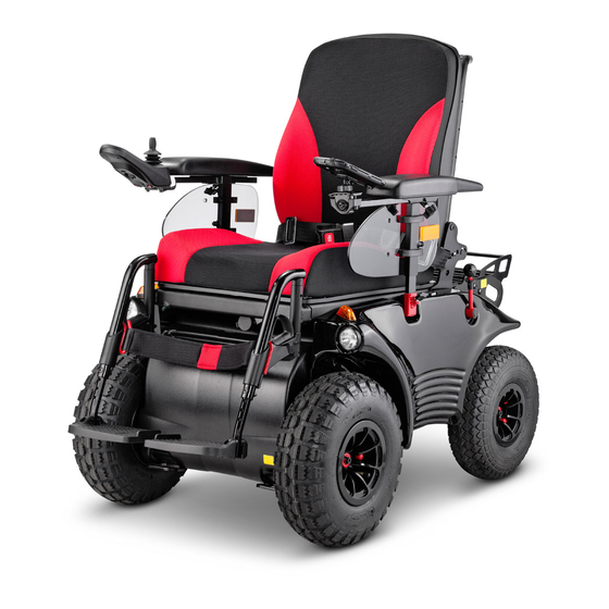
Page 10: Overview
OVERVIEW Model: 2.322 The overview shows the most important components and operating devices of the electric wheelchair. Pos. Description (13) Selection lever drive/push mode resp. (1) Back support brake lever (2) Arm support (14) Direction indicator light / back light (3) Seat (15) Rear transport attachment (4) Leg support... -
Page 11: Handling The Electric Wheelchair
HANDLING THE ELECTRIC steering lever) while driving as well as the preadjusted maximum final speed of your WHEELCHAIR electric wheelchair. Entering resp. exiting the electric wheel- chair may only be conducted with the BRAKES electric wheelchair switched off and the brakes engaged. -
Page 12: Drum Brake
Drum Brake For optimal braking effect the drum brake is to be kept free of grease, oil, gunge and dust. – Danger of accident! The brake performance reduces with the wear on the brake pads. Any decrease in braking performance must be repaired immediately by your specialist workshop. -
Page 13: Drive-/Push Mode
Drive-/push mode The electric wheelchair may only be switched to push mode when it is stand- ing still or in case of emergencies, but never on slopes/hills. The Selection lever drive/push mode is lo- cated on the side opposite to the operating module. -
Page 14: Selecting The Operation
SELECTING THE OPERATION In order to obtain operational readiness of the electric wheelchair the following direc- tions are to be carried out in the indicated order. ☞ Charge the drive batteries via the oper- ating module before the first journey. Establish drive mode [1]. -
Page 15: Pre-Operation Checks
Pre-operation checks Before starting to drive, the following should be checked: – the battery charging condition, – the setting of the preselected final speed. ☞ For this observe the operating man- ual < Operating module >. Battery charging procedure Do not insert any objects other than the battery charger plug into the battery charging socket. -
Page 16: Positioning The Operating Module
Positioning the operating module Switch off the operating module before adjusting/removing it. Function description You will find a detailed description of the keys and symbols in the operating manual for < Operating module >. The position of the operating module can be adjusted to suit the individual size of the user. -
Page 17: Swivelling The Operating Module
Swivelling the operating module Do not grab into the area of the cross brace. – Danger of squashing! The power of the magnets (3) can be re- duced, for example with tape on top of the magnets, for easier swivelling of the operating module. -
Page 18: Leg Supports
LEG SUPPORTS Before any actions on the leg supports the wheelchair is to be secured against unintentional rolling motions. ☞ Therefore observe chapter Securing the electric wheelchair on page 11. Calf belt Do not drive without the calf belt. – Dan- ger of accident! The removable calf belt (1) prevents the feet from sliding off the back of the footplates. -
Page 19: Lower Leg Support
Lower leg support The footplates, resp. footboard needs to be folded up before entry or exit [1]. ☞ Check the locking points! – Remove both feet from the footplates. – Fold both footplates up toward the side [1]. ☞ Before starting to drive the footplates resp. -
Page 20: Leg Support Upper Part
Leg support upper part The upper leg support with an inserted lower leg support is termed leg support. Turning the leg supports to the side Leg supports turned to the side are re- leased automatically and can easily come off. When the electrically height adjustable leg supports are removed the electric contact (4) needs to be protected from... -
Page 21: Swivelling In The Leg Supports
Swivelling in the leg supports For inward swivelling, let the leg supports swivel forward until the lock audibly engag- es [1]. ☞ After audibly swivelling the leg sup- ports inward check the respective lock- ing device. ☞ Afterwards observe the chapter Lower leg support on page 19. -
Page 22: Height Adjustable Leg Support
Height adjustable leg support Never put the free hand into the adjust- ment mechanism while adjusting the height adjustable leg support. – Danger of jamming! Have the leg support that is to be adjust- ed secured against falling away by an ac- companying person. -
Page 23: Arm Supports
ARM SUPPORTS Do not use the arm supports to lift or car- ry the wheelchair. Do not drive without the arm supports. Ensure the tight fit of the clamping screw (3) in order to prevent the arm support from sliding down. Arm supports, code 106 The removable arm supports [1]+[2] can be adjusted in height to the demands of the... -
Page 24: Arm Supports Code 24 - Ergostar Seat
Arm supports code 24 - Ergostar seat Swivel up the arm supports The arm supports can be swivelled up for an easier transfer to/from the seat [1]. Adjusting the angle of the arm support By turning the adjustment wheel (2) the an- gle of the arm support can be adjusted. -
Page 25: Seat
SEAT Swivelling up the seat Do not hold onto the leg supports to swivel the seat up. ☞ Remove the leg supports if necessary. ☞ Always remove the electrical leg sup- ports. ☞ Grab under the front edge of the seat pad for upward swivelling. -
Page 26: Seat Ergostar
Seat Ergostar Adjustment of the back support angle To adjust the angle of the back support the locking lever (2) must be pressed down- ward. Let the locking lever latch at the next latch- ing position after having adjusted the back support angle [1]. -
Page 27: Ergo Seat
Ergo Seat The back support can be folded down for storage or transport. ☞ For better demonstration of the wire cable (1) the back support is shown without cushion. Folding over the back support If required remove the seat pad (velcro fas- tener). -
Page 28: Electrically Adjustable Back Support
Electrically adjustable back support Only adjust the back support when the electric wheelchair is standing on a level surface. A danger of tipping over exists on gradi- ents. The back support [1] is electrically adjusta- ble. ☞ Note: Herefore view the operating manual <... -
Page 29: Lap Belt
LAP BELT Make sure that no objects are trapped between belt and the body! – Thus you avoid painful pressure points. The lap belt is not part of the retaining system for the electric wheelchair and/or the driver during transport in motor vehi- cles. -
Page 30: Head Support
HEAD SUPPORT Always adjust the upper edge of the head support close to the back of the head and at about eye level. Do not position the head support at neck height. We recommend the fitting of two rear- view mirrors for driving with a head sup- port. -
Page 31: Rear-View Mirror
REAR-VIEW MIRROR Removing the rear-view mirror To remove the rear-view mirror loosen the clamping screw (1) and pull the rear-view mirror forward out of the arm support tube. ☞ Carefully place the rear-view mirror down and protect the mirror glass from strain or other objects. -
Page 32: Loading And Transportation
< Sicherheit mit Meyra-Rollstühlen, auch might limit or forbid the transportation. bei der Beförderung im Kraftfahrzeug >! – This document and further informa- tion can be accessed on our website < www.meyra.com > in the < Download Archive >. -
Page 33: Transport In Public Methods Of Transportation
Transport public methods transportation National regulations may prevent taking them on busses or trains. Inform yourself at the transportation com- panies concerning limitations. Your electric wheelchair is not designed for user transport in public transportation vehi- cles. We recommend use of one of the firm- ly built in seats of the public vehicle. -
Page 34: Transport Security
Transport security Carry out the following steps when the electric wheelchair is located in the trans- port vehicle: Establish electrical safety ☞ For this observe the regulations of the respective transport company. – Switch the electric wheelchair off. – Selecting the motor mode.- There- fore swivel the selection lever drive- / push mode to drive mode. -
Page 35: Maintenance Schedule
Maintenance schedule WHEN WHAT REMARK Before starting out General Carry out test yourself or with a helper. Test for faultless operation. Checking the magnet- Carry out test yourself or with ic brake a helper. Switch the selection le- If the electric wheelchair can ver drive- / push mode to be pushed, have the brakes drive mode. - Page 36 WHEN WHAT REMARK Every 2 months Check tyre profile Carry out a visual check your- (depending dis- self or with a helper. Minimum tread = 1 mm tance covered) If the tyre profile is worn down or if the tyre is damaged, con- sult a specialist workshop for repairs.
-
Page 37: Fuses
Fuses Only replace the safety fuse with a safety fuse of the same type! Replacing the fuses Before replacing fuses, park the electric wheelchair on a level surface and secure it from rolling away. ☞ Therefore observe chapter Securing the electric wheelchair on page 11. -
Page 38: Lighting
Lighting ☞ If a turn-signal bulb is defective, the re- maining one blinks at double frequen- ☞ When replacing always use bulbs with the same performance data. Adjusting the headlights Vertical alignment The headlights should be set in such a way that the light cone is visible on the road. -
Page 39: Fault Correction
Fault correction Fault Cause Remedy LED/LCD-display of the Main-/battery fuse is de- Replace defective fuse or operating module is not lit fective or not correctly in- clean contacts and insert after switching it on. serted. correctly. Plug connection of the Check the plug connec- power supply... -
Page 40: Basic Safety Information
BASIC SAFETY The braking force transferred to the driving surface is much less on a downward slope INFORMATION than on a level driving surface and is fur- ther reduced by poor road conditions (e.g. Transfer out of the electric rain, snow, grit, dirt). A dangerous slipping wheelchair of the wheels due to excessive braking and an associated unwanted course deviation... -
Page 41: Driving On Public Highways
Always maintain a safety distance between the wheelchair and drops, stairs and similar obstacles sufficient for reaction, braking and turning. Driving on public highways Your electric wheelchair is equipped by the manufacturer with reflectors. With limited visibility and especially in the dark we recommend to mount active light- ing equipment and to turn it on in order to see better and be seen. -
Page 42: Service
SERVICE ☞ Remove spots with a sponge or a soft brush. – Wash off persistent dirt with com- Tyres mercial fine detergent. The following items need to be checked: ☞ Do not soak! Do not machine wash! – the air pressure (only on pneumatic tyres) Follow-up with clean water and allow to dry. -
Page 43: Disinfection
Disinfection Repairs If the product is used by more than one per- Trustfully contact your local specialist dealer son (for example in a care centre), the use of of another specialist workshop for carrying a commercial disinfectant is mandatory. out repairs. They are briefed in carrying out the work and have educated personnel. -
Page 44: Disposal
Disposal – Level, firm driving surface. The maximum range is greatly reduced by: – frequent uphill driving, – insufficient charging condition of the drive batteries, – low ambient temperature (e.g. in win- ter) – frequent acceleration and braking (e.g. in city traffic) The disposal must comply with the respec- –... -
Page 45: Values Acc. To Iso 7176-15 For Model 2.322
Values acc. to ISO 7176-15 for model 2.322 Overall length with leg support Overall width Overall dimensions User weight (incl. additional load) – kg Weight of the heaviest part Actual seat depth – mm Actual seat width Folding length – mm –... -
Page 46: Further Technical Data For Model 2.322
Further technical data for model 2.322 Sound level < 70 dB(A) Protection class IP X4 Turning area Drive controller 24 V / 100 A Engine output Main fuse Lighting 6 V / 12 V Additional load – kg Permitted axle load front –... - Page 47 Drive batteries 2 x 12 V 43 Ah (5 h) / 50 Ah (20 h) sealed Max. battery dimensions (LxWxH) Charging current 12 A...
-
Page 48: Technical Data
TECHNICAL DATA Model 2.322 All data within the following table relates to the standard version of the stated model. Dimensional tolerance ± 1.5 cm, ± 2°. Model: ........................Electric wheelchair model 2.322 Type plate: ........................rear right on the main frame Class of use as per DIN EN 12184: ............... B - Optimus 2 / C - Optimus 2 S Life span: .................................. - Page 49 Dimensions with seat Ergostar (Code 961 without head support): Length incl. footplates: ............................1190 mm General width: ................................680 mm Height: ..................................1170 mm Seat depth: ..................................50 cm Seat width with code 24: ............................50 cm Seat width with code 106 (min. / max.): ....................43 / 56 cm Seat width with code 106 (manufacturers setting): ................50 cm Seat height: ..................................
- Page 50 Transport dimensions with seat Recaro (without leg supports, without head support): Length (back support toward the front): ....................1030 mm Length (back support toward the back): ....................1260 mm Width: ....................................680 mm Height (back support toward the front): ....................900 mm Height (back support toward the back): ....................800 mm Tyres: Steering wheel (rear): ....................
- Page 51 Battery charger: for batteries up to 65 Ah (20 h) ........................24 V / 6 A for batteries up to 85 Ah (20 h) ........................24 V / 8 A for batteries up to 125 Ah (20 h) ........................ 24 V / 12 A max.
- Page 52 Weights (basic equipment): The values in the brackets ( ) are valid for vehicles with 15 km/h: max. permissible total weight 6 km/h / 10 km/h / (15 km/h): .......... 330 / (300) kg permitted axle load front: ........................210 / (190) kg permitted axle load rear: ..........................
-
Page 53: Meaning Of The Labels On The Electric Wheelchair
Meaning of the labels on the electric wheelchair Attention! Read the operating manuals and other provided documen- tation. Do not lift the electric wheelchair at the arm supports or leg supports. Removable parts are not suitable for carrying. Drive mode Switching to push mode with the selection lever right. -
Page 54: Meaning Of The Symbols On The Type Plate
Meaning of the symbols on the type plate Manufacturer Order number Serial number Production date (Year – Calendar week) Permitted user weight max. permissible total weight Permitted axle weights Max. permissible rising gradient Max. permissible falling gradient Permitted maximum speed The product is approved as a seat within a motor vehicle The product is not approved as a seat within a motor vehicle. -
Page 55: Meaning Of The Symbols On The Washing Instruction
Meaning of the symbols on the washing instruction (the symbols correspond to European standard) Wash as delicates with the indicated maximum temperature in °C Wash as regular laundry with the indicated maximum temperature in °C Do not bleach Not suited for the dryer Do not iron Do not dry-clean... -
Page 56: Inspection Certificate
INSPECTION CERTIFICATE Recommended safety inspection 1st year (at least every 12 months) Vehicle data: Stamp of specialist dealer: Model: Signature: Delivery note no.: Place, date: Serial-no.(SN): Next safety inspection in 12 months Date: Recommended safety inspection 3rd year Recommended safety inspection 2nd year (at least every 12 months) (at least every 12 months) Stamp of specialist dealer:... -
Page 57: Notes
NOTES... -
Page 58: Warranty / Guarantee
WARRANTY / GUARANTEE Interferences through radiation sources such as mobile phones with high trans- mission power, HiFi-equipment and other We accept legal liability for this product extreme interference radiators outside of within the scope of or general terms and norm specifications cannot be declared as conditions and warranty and the guaran- warranty or guarantee claims. -
Page 59: Warrantee / Guarantee Section
Warrantee / Guarantee section Please fill out! Copy if necessary and send the copy to the specialist dealer. Warranty / Guarantee Model designation: Delivery note no.: SN (view type plate): Date of delivery: Stamp of the specialist dealer: Inspection certificate for transfer Vehicle data: Serial-no.(SN): Stamp of specialist dealer:... - Page 60 Your specialist dealer MEYRA GmbH Meyra-Ring 2 D-32689 Kalletal-Kalldorf +49 5733 922 - 311 +49 5733 922 - 9311 info@meyra.de www.meyra.de MEYRA 205 340 001 (Status: 2017-02) All technical modifications reserved. Original operating manual.
Need help?
Do you have a question about the Oprtimus 2 and is the answer not in the manual?
Questions and answers